Bus duct

A technology of bus duct and side plate, applied in the field of bus duct, can solve the problems of high cost, complicated installation, corrosion, etc., and achieve the effect of simple manufacturing process, convenient installation and transportation, and good corrosion resistance.

Inactive Publication Date: 2018-06-15
镇江凯勒电力科技有限公司
View PDF0 Cites 1 Cited by
  • Summary
  • Abstract
  • Description
  • Claims
  • Application Information

AI Technical Summary

Problems solved by technology

[0002] In the low-voltage power transmission and distribution industry, the joints between the sections of the busway products are connected and conducted through the connector. The width of the connector is usually larger than the width of the main product of the busway. The connector must pass through the connector before it can be connected to the busway The side panels of the main product are connected. The traditional side panel connectors are generally made of Q235 steel plates, which are heavy, inconvenient for installation and transportation, and are prone to rust due to factors such as rain and fog. The surface treatment process is troublesome; the side panel connectors and joints Connectors need to be connected through an adapter plate, and an insulating bushing needs to be set between the adapter plate and the joint bolts. The butterfly spring of the connector is in direct contact with the outermost insulating partition of the connector, and the connection effect is not good. Large quantity, cumbersome installation, cumbersome manufacturing process, high cost, low heat dissipation efficiency of joints, resulting in high temperature rise of busbar system; temperature rise of connectors is an important indicator for testing the safety performance of busway products, traditional connectors have low heat dissipation efficiency

Method used


Image

  • Bus duct
  • Bus duct
  • Bus duct

Examples


Embodiment Construction

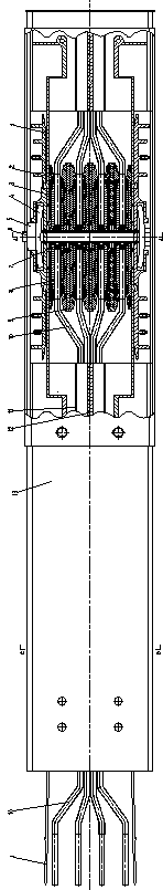
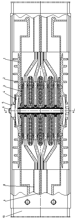
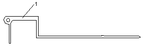
[0018] As shown in the figure, a bus duct includes a housing composed of a side plate 12 and a cover plate 13, and a phase line conductor 10 placed in the inner cavity of the housing; the bus duct side plate 12 and the cover plate 13 of the embodiment of the present invention are One-piece pultruded one-piece side cover plate, the left and right two-part one-piece side cover plate can use profiles of different cross-sections to cooperate with each other to form a shell, and profiles of the same cross-section can also be used to cooperate with each other to form a shell; the shoulder of the side plate Auxiliary support plates 11 can be provided to improve the support strength of the side plates and at the same time improve the protection level to prevent the accumulation of dust and rain; the sections of the bus duct are connected through connectors;

[0019] The connector includes a number of insulating partitions 3, conductor connecting pieces 8 and heat sinks 9 distributed at...


PUM


Abstract

The invention relates to a bus duct. A casing composed of side plates and a cover plate is internally provided with a phase wire conductor, segments of the bus duct are connected through joint devices, joint bolt end portions of the joint devices, joint nuts and joint pressure plates among outer-most-layer insulation baffle plates are formed by section bars through one-time pultrusion molding, cross sections of the section bars are generally C-shaped structures, a wing-edge outer side of the C-shaped structures is provided with multiple heat radiation reinforcement ribs, an inner side is provided with limit grooves for limiting side plate connection members, right-angle connection portions of long edges and short edges of the side plate connection members are provided with reinforcement ribs projecting outwards, and centers of the reinforcement ribs have thread connection holes. The bus duct is advantaged in that disc-shaped springs are clamped in inner chambers of the C-shaped structures of joint device pressure plates, width dimensions of opening portions of the C-shaped structures of the joint device pressure plates mutually adapt to width dimensions of the joint nuts, materialsof the joint device pressure plates and the side plate connection members are aluminum alloy, the quantity of parts is small, connection is reliable, mounting and transportation are convenient, corrosion resistance performance is good, weight is light, and appearance is attractive.

Description

technical field [0001] The invention relates to a bus duct, which is specifically applied to the technical field of manufacture and installation of bus duct products in the low-voltage power transmission and distribution industry. Background technique [0002] In the low-voltage power transmission and distribution industry, the joints between the sections of the busway products are connected and conducted through the connector. The width of the connector is usually larger than the width of the main product of the busway. The connector must pass through the connector before it can be connected to the busway The side panels of the main product are connected. The traditional side panel connectors are generally made of Q235 steel plates, which are heavy, inconvenient for installation and transportation, and are prone to rust due to factors such as rain and fog. The surface treatment process is troublesome; the side panel connectors and joints Connectors need to be connected thro...

Claims


Application Information

Patent Timeline
Patent Type & Authority Applications(China)
IPC IPC(8): H02G5/06H02G5/10
CPCH02G5/06H02G5/10
Inventor 王加慧
Owner 镇江凯勒电力科技有限公司
Why Eureka
Try Eureka