Target monitoring method and target monitoring system
A target monitoring and target object technology, which is applied in CCTV systems, components of TV systems, TVs, etc., can solve the problems that affect the real-time performance of target monitoring and cannot track multiple target objects in time, and achieve the effect of improving real-time performance.
- Summary
- Abstract
- Description
- Claims
- Application Information
AI Technical Summary
Problems solved by technology
Method used
Image

Examples
Embodiment 1
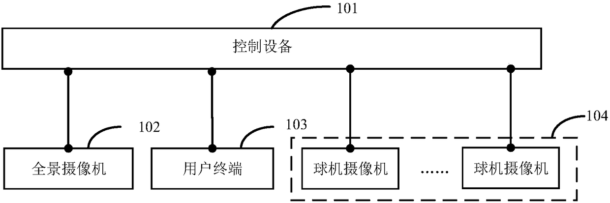
[0051] A target monitoring method provided by an embodiment of the present invention is applied to a target monitoring system. The above target monitoring system is as follows: figure 1 As shown, it includes: a control device 101, a panoramic camera 102, a user terminal 103, and more than two dome cameras 104 respectively connected to the control device 101.
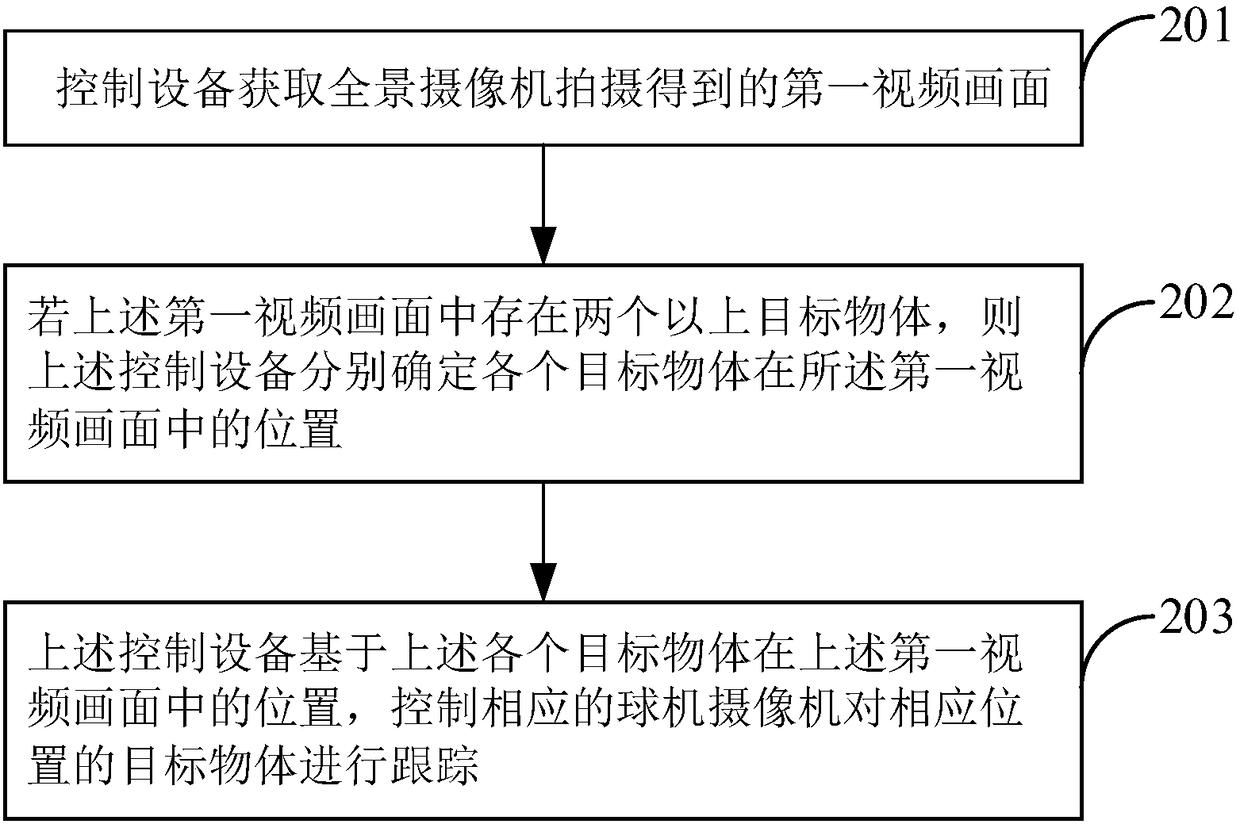
[0052] figure 2 Provides a schematic flow chart of a target monitoring method, such as figure 2 As shown, the above target monitoring methods include:
[0053] Step 201, the control device acquires the first video picture captured by the panoramic camera;
[0054] In the embodiment of the present invention, the above-mentioned panoramic camera is a camera that can monitor a larger scene from all angles, and can realize uninterrupted shooting of the same larger scene, which can solve the problem of the small shooting range of ordinary cameras and the inconsistency of various monitoring pictures. coherent question. Opt...
Embodiment 2
[0069] Another target monitoring method provided by the embodiment of the present invention is applied to a target monitoring system. The above target monitoring system is as follows: figure 1 As shown, it includes: a control device 101, a panoramic camera 102, a user terminal 103, and more than two dome cameras 104 respectively connected to the control device 101.
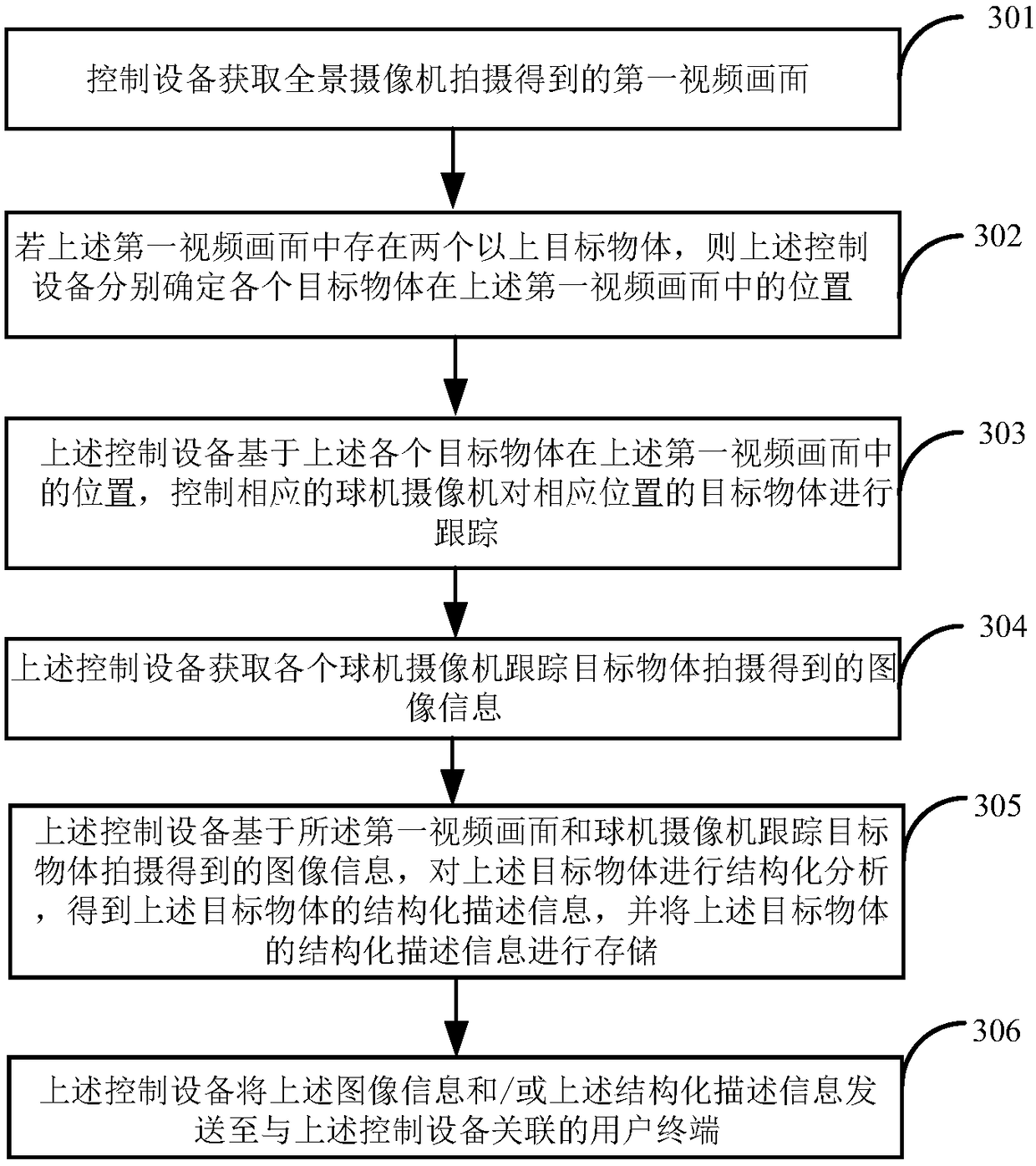
[0070] image 3 Provides a schematic flow chart of a target monitoring method, such as image 3 As shown, the above target monitoring methods include:
[0071] Step 301, the control device acquires the first video picture captured by the panoramic camera;
[0072] Step 302, if there are more than two target objects in the above-mentioned first video frame, the above-mentioned control device respectively determines the positions of each target object in the above-mentioned first video frame;
[0073] Step 303, the above-mentioned control device controls the corresponding dome camera to track the target object at...
Embodiment 3
[0085] Figure 4 It is a schematic structural diagram of a target monitoring system using two dome cameras as an example provided by the embodiment of the present invention. For the convenience of description, only the parts related to the embodiment of the present invention are shown, such as Figure 4 As shown, the target monitoring system in the embodiment of the present invention includes: a control device 401, and a panoramic camera 402, a user terminal 403, and a dome camera 404 respectively connected to the control device 401, wherein the dome camera 404 includes a dome camera 4041 and dome camera 4042.
[0086] In the embodiment of the present invention, the connection between the panoramic camera 402, the user terminal 403 and the dome camera 404 and the control device 401 may be wireless or wired.
[0087] The panoramic camera 402 includes: N lenses, where N is not less than 2;
[0088] The control device 401 includes a first acquisition unit 4011, a determination ...
PUM
 Abstract
Description
Claims
Application Information
 - R&D
- Intellectual Property
- Life Sciences
- Materials
- Tech Scout
- Unparalleled Data Quality
- Higher Quality Content
- 60% Fewer Hallucinations
Browse by: Latest US Patents, China's latest patents, Technical Efficacy Thesaurus, Application Domain, Technology Topic, Popular Technical Reports.
© 2025 PatSnap. All rights reserved.Legal|Privacy policy|Modern Slavery Act Transparency Statement|Sitemap|About US| Contact US: help@patsnap.com