Deflection fixture for machining

A fixture and displacement technology, which is applied in the direction of manufacturing tools, workpiece clamping devices, metal processing equipment, etc., can solve the problems of inconvenient positioning and clamping of square steel plates, and uneven positions of square steel plates, so as to facilitate subsequent surface processing , Convenient positioning and clamping, automatic and automatic clamping effect

Inactive Publication Date: 2018-06-19
WUHU HENGHAO MACHINERY MFG
View PDF6 Cites 0 Cited by
  • Summary
  • Abstract
  • Description
  • Claims
  • Application Information

AI Technical Summary

Problems solved by technology

When surface processing parts with a relatively simple structure and a large quantity such as a square steel plate, only a fixture with a simple structure and easy to use is required, but the problem is that the pin holes on the square steel plate are often in different positions, which in turn leads to It is inconvenient to locate and clamp

Method used


Image

  • Deflection fixture for machining
  • Deflection fixture for machining

Examples


Embodiment Construction

[0014] In order to enable those skilled in the art to better understand the technical solutions of the present invention, the present invention will be described more clearly and completely below in conjunction with the accompanying drawings in the embodiments. Of course, the described embodiments are only a part of the present invention. Not all, based on this embodiment, other embodiments obtained by those skilled in the art without creative efforts are all within the protection scope of the present invention.

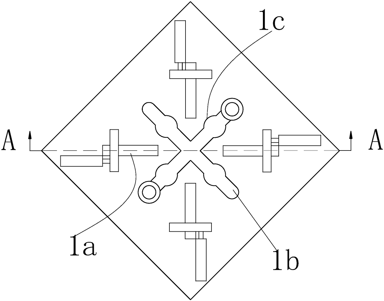
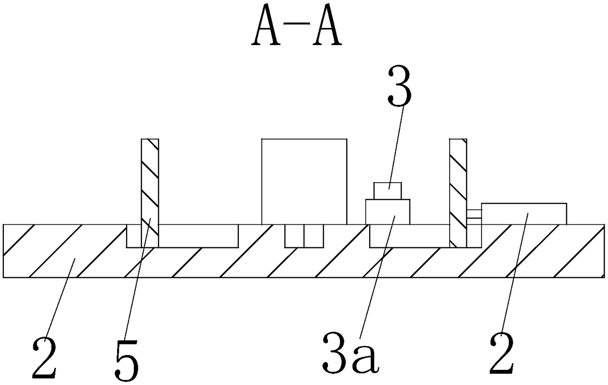
[0015] Such as Figure 1 to Figure 2 As shown, a displacement fixture for processing includes a base plate 1, a cross-shaped blind groove 1b is provided in the center of the base plate 1, and two positioning pins 3 are slidably installed in the blind groove 1b. The front left side, the front right side, the rear left side, and the rear right side are all provided with expansion slots 1c, and each positioning pin 3 is vertically slidably mounted with a fixed ring slee...


PUM


Abstract

The invention relates to a deflection fixture for machining. The deflection fixture for machining comprises a base plate; a cross blind groove is formed in the center of the base plate; two dowel pinsare slidingly mounted in the blind groove; expansion grooves are formed in the front left side, the front right side, the back left side and the back right side in the blind groove; and a fixed ringsleeve is vertically and slidingly mounted on each dowel pin. Chutes are formed in the forward front side, the forward back side, the forward left side and the forward right side on the base plate; aclamping plate is slidingly mounted in each chute; and each clamping plate is connected with a cylinder. The deflection fixture for machining is convenient to use, can conveniently adjust the positions of two dowel pins, realizes convenient positioning and clamping of multiple square steel plates with different pin hole positions, and can quickly and automatically clamp the square steel plates toachieve subsequent surface machining.

Description

technical field [0001] The invention relates to a fixture, in particular to a displacement fixture for processing. Background technique [0002] Generally speaking, the fixture mainly refers to the device used to fix the processing object in the process of mechanical manufacturing so that it occupies the correct position to accept construction or inspection. When surface processing parts with a relatively simple structure and a large quantity such as a square steel plate, only a fixture with a simple structure and easy to use is required, but the problem is that the pin holes on the square steel plate are often in different positions, which in turn leads to It is inconvenient to locate and clamp. Contents of the invention [0003] Now in order to overcome the defects of the above-mentioned technologies, the present invention proposes a displacement fixture for processing. [0004] The technical problem to be solved by the present invention adopts the following technical ...

Claims


Application Information

Patent Timeline
Patent Type & Authority Applications(China)
IPC IPC(8): B23Q3/08B25B11/00
CPCB23Q3/08B23Q2703/04B25B11/00
Inventor 袁道华
Owner WUHU HENGHAO MACHINERY MFG
Why Eureka
Try Eureka