
Load reduction control method of wind power generation unit based on blade root load and tower frame load

A technology for a wind turbine generator set and a control method, which is applied in the control of wind turbines, wind turbines, and engine control, and can solve problems such as reducing the operating load of the wind turbine.

Active Publication Date: 2018-06-19
GUANGDONG MINGYANG WIND POWER IND GRP CO LTD
View PDF8 Cites 20 Cited by
  • Summary
  • Abstract
  • Description
  • Claims
  • Application Information

AI Technical Summary

Problems solved by technology

However, through these load signals, how to effectively reduce the operating load of the unit and how to participate in the load reduction control has not been explored more

Method used


Image

  • Load reduction control method of wind power generation unit based on blade root load and tower frame load
  • Load reduction control method of wind power generation unit based on blade root load and tower frame load
  • Load reduction control method of wind power generation unit based on blade root load and tower frame load

Examples


Embodiment Construction

[0051] The present invention will be further described below in conjunction with specific examples.

[0052] The load reduction control method of the wind power generating set based on the blade root load and the tower load provided in this embodiment includes the following steps:

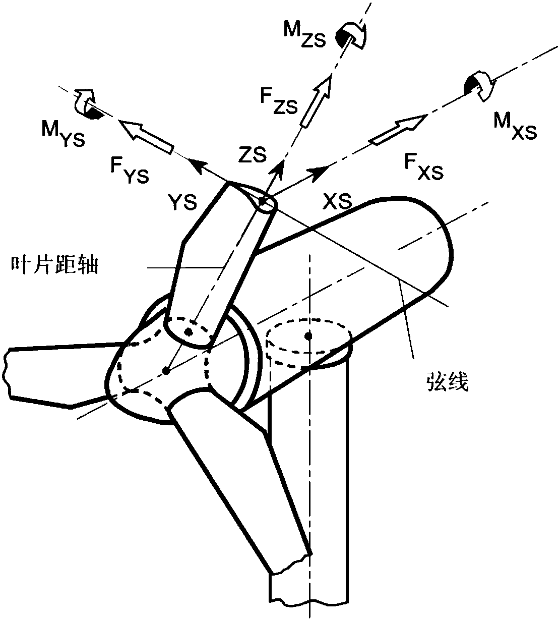
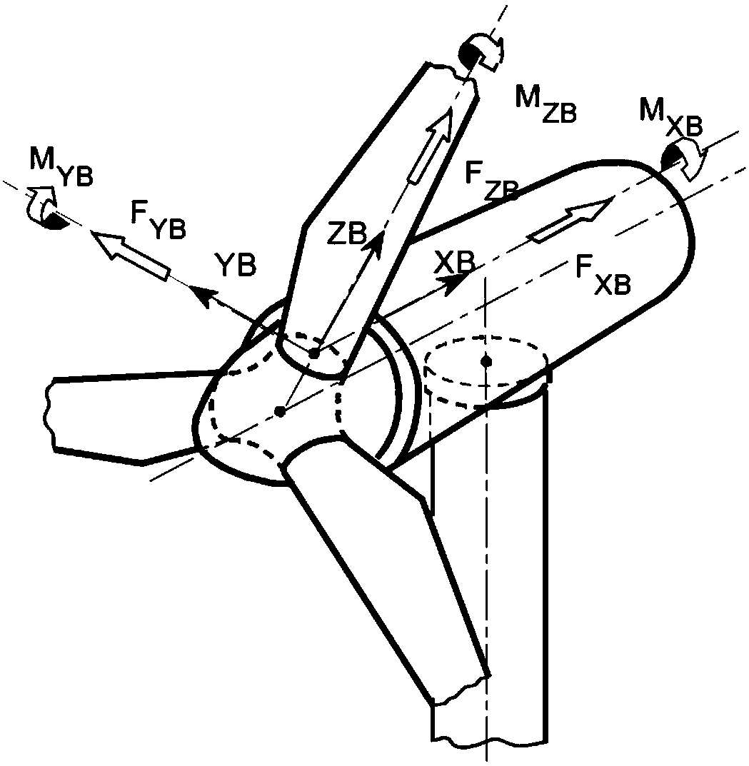
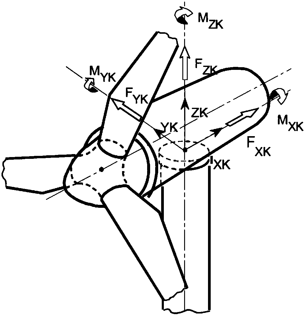
[0053] 1) Install a load sensor at the root of each blade of the wind turbine impeller, and directly measure the bending moment M of the blade root in the swinging direction through the sensor Flap and bending moment M in shimmy direction Edge , the out-of-plane bending moment M of the blade root is calculated OutPlane and root in-plane bending moment M InPlane . Bending moment M outside the blade root surface OutPlane It reflects the load of the blade root in the thrust direction of the impeller, and the in-plane bending moment M of the blade root InPlane It reflects the load of the blade root in the direction of impeller rotation.

[0054] Blade root swinging moment M Flap and bending mome...


PUM


Abstract

The invention discloses a load reduction control method of a wind power generation unit based on a blade root load and a tower frame load. The load reduction control method comprises the following steps that 1) a load sensor is attached to the root of each blade of an impeller to directly measure a root flapping direction moment and a root swaying direction moment of each blade, and calculation isperformed to obtain a blade root surface outer moment and a blade root surface inner moment; 2) load sensors are attached to the top end and the bottom end of a tower drum respectively, a tower top moment is measured, a tower top pitching direction moment and a tower top left-and-right direction moment are calculated according to a conversion formula, a tower bottom moment is measured, and a tower bottom pitching direction moment and a tower bottom left-and-right direction moment are calculated according to the conversion formula; 3) a limit load, a safety factor and a load trigger flag are defined; and 4) whether the unit triggers the load limitation or not can be judged through a Flag bit, and corresponding control can be adopted when the load is triggered. By adopting the load reduction control method provided by the invention, load reduction control of the unit can be realized, the load of the unit under the limit working condition is lowered, and safety running of the unit is guaranteed.

Description

technical field [0001] The invention relates to the technical field of load reduction control of wind turbines, in particular to a load reduction control method of wind turbines based on blade root load and tower load. Background technique [0002] It is known in the industry that with the development of wind power technology, wind turbines are constantly developing towards large megawatt models, flexible high towers, large impellers and lightweight units. The single-unit capacity of wind turbines has gradually developed from 1MW and 2MW to 3MW, 5MW, 7MW and even 10MW. Not only that, the operating environment of wind turbines has gradually changed from plains to mountains, from low turbulence to high turbulence and high wind shear, and from land to ocean. For large impeller units, the diameter of the impeller increases significantly, and the wind speed change at any point in the impeller plane will be sensed by the entire rotor plane, and the impact of wind turbulence on th...

Claims


Application Information

Patent Timeline
Patent Type & Authority Applications(China)
IPC IPC(8): F03D7/04
CPCF03D7/043F05B2270/328F05B2270/331Y02E10/72
Inventor 李刚马冲黄国燕陈思范
Owner GUANGDONG MINGYANG WIND POWER IND GRP CO LTD
Learn More