Outlet housing for range hood

A technology for air outlet hoods and range hoods, which is applied in the direction of removing oil fumes, applications, household stoves, etc. It can solve the problems that the oil fume cannot be discharged normally, the opening and closing status of the valve cannot be detected in real time, and the oil fume is poured back, etc., to achieve conduction and isolation Easy to operate, easy to disassemble and replace, and reduce energy consumption

Active Publication Date: 2018-06-19
JOYOUNG CO LTD
View PDF4 Cites 2 Cited by
  • Summary
  • Abstract
  • Description
  • Claims
  • Application Information

AI Technical Summary

Problems solved by technology

However, the electric check valve cannot detect the opening and closing state of the valve plate in real time. Once the valve plate switch action fails, it is easy to cause the oily fume to be unable to be discharged normally or cause the oily fume to flow backward.

Method used


Image

  • Outlet housing for range hood
  • Outlet housing for range hood
  • Outlet housing for range hood

Examples


Embodiment 1

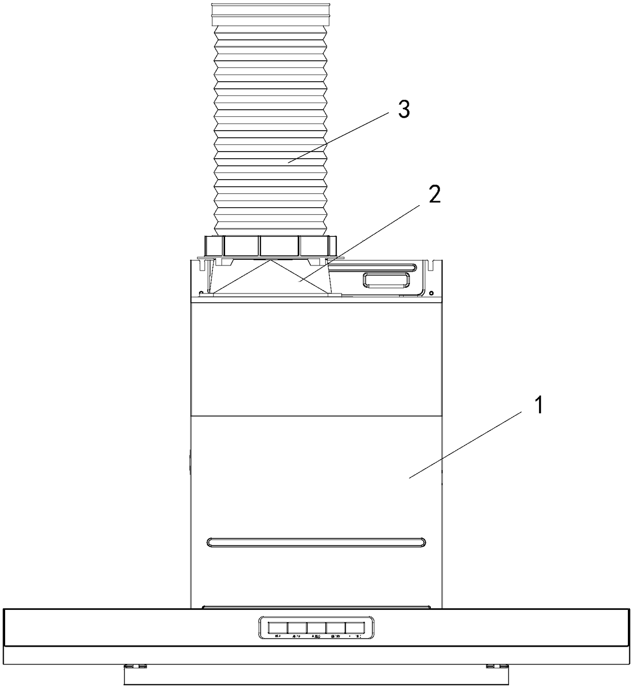
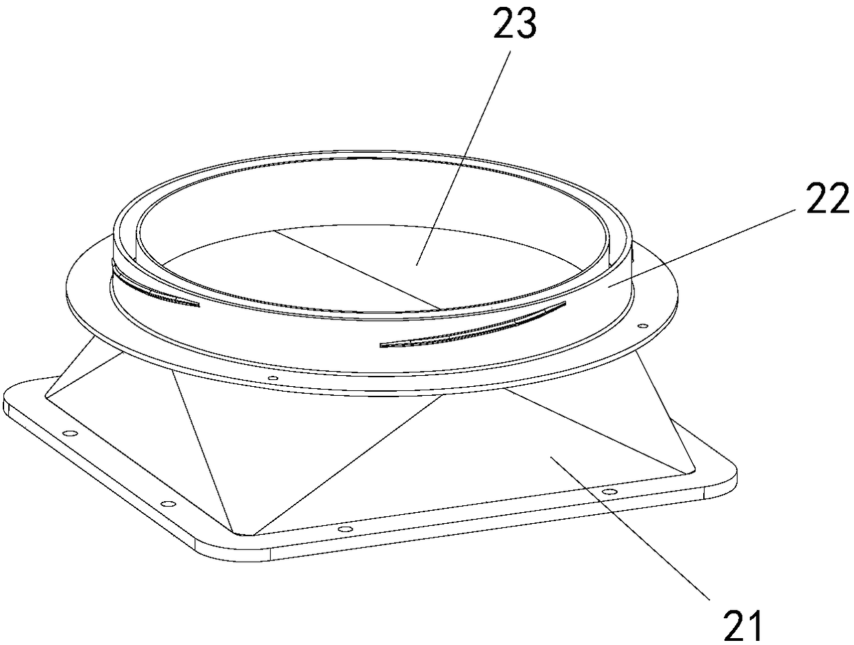
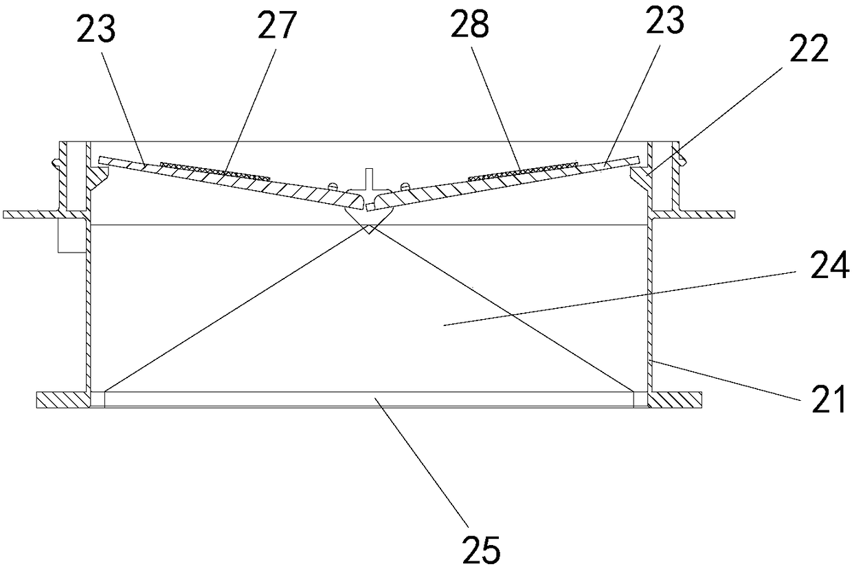
[0041] Such as Figure 1-5 As shown, the present embodiment provides an air outlet cover for a range hood. The air outlet cover 2 includes a lower cover 21 connected to the range hood 1, a mounting ring 22 connected to the air outlet pipe 3, and a stopper that can be turned over and opened. The valve leaf 23 of the return valve, the air outlet cavity 24 of the air outlet cover is formed in the lower cover 21 and the installation ring 22, the air inlet opening 25 of the air outlet cover 2 is formed at the bottom of the lower cover 21, and the installation ring The top of 22 forms the air outlet opening 26 of the air outlet cover 2, and the valve blades 23 are two valve blades that rotate relatively. The leaves 23 can be flipped open or closed respectively, so as to conduct or cut off the air inlet opening 25 and the air outlet opening 26, the two valve leaves 23 can form a relative valve leaf angle α, and the air outlet cover 2. Output the corresponding detection capacitance v...

Embodiment 2

[0052] The difference between the present embodiment and the first embodiment is that the positive and negative conductive electrode plates are glued and fixed to the valve leaf.

[0053] Such as Figure 6 As shown, the positive and negative conductive plates 27, 28 and their corresponding valve leaves 23 are fixed by gluing, and the two valve leaves 23 are respectively provided with overflowing glue that matches the positions of the positive and negative conductive plates 27, 28. Hole 5, this setting improves the uniformity of the glue overflow, and the thickness of the adhesive layer between the valve leaf 23 and the positive and negative conductive plates is uniform, which is conducive to the generation of capacitance between the positive and negative conductive plates, and is glued and fixed through the glue overflow hole 5 The valve leaf 23 and the conductive electrode plate enhance the installation reliability of the positive conductive electrode plate 27 and the negativ...

Embodiment 3

[0055] The difference between this embodiment and the first embodiment is that the positive and negative conductive plates are clipped and fixed with the valve leaf.

[0056] Such as Figure 7 As shown, the positive and negative conductive plates 27, 28 and their corresponding valve leaves 23 are fixed by clamping, and the two valve leaves 23 are respectively provided with card slots 6, and the positive and negative conductive plates 27, 28 Installed in the card slot 6, when installing, respectively install the positive conductive electrode plate 27 and the negative conductive electrode plate 28 into the card slot 6, and limit and fix the positions of the positive and negative conductive electrode plates and the positive and negative conductive electrode plates through the buckle 10 , so that the positive and negative conductive plates are firmly held in the slot 6 to prevent the plates from loosening.


PUM


Abstract

The invention provides an outlet housing for a range hood. The outlet housing comprises a lower housing connected with the range hood, an installation ring connected with an air outlet pipe, and valveblades capable of being turned over to be opened. The lower housing and the installation ring form an air outlet cavity of the outlet housing; an air inlet opening of the outlet housing is formed inthe bottom part of the lower housing; an air outlet opening of the outlet housing is formed in the top part of the installation ring; the valve blades are two valve blades rotating oppositely; the twovalve blades are connected into the air outlet cavity through a rotary shaft, and can be turned over to be opened or closed so as to connect or disconnect the air inlet opening and the air outlet opening; the two valve blades can form an opposite valve blade included angle ranging from 0 degree to 180 degrees; and the outlet housing outputs a corresponding detection capacitance value according tothe valve blade included angle. The two valve blades with different polarities can form a variable capacitance device, the outlet housing outputs the corresponding detection capacitance value according to the valve blade included angle, and the range hood can judge an open-close state of the valve blades according to the capacitance value detected in real time.

Description

technical field [0001] The invention relates to the field of kitchen household appliances, in particular to an air outlet cover for a range hood. Background technique [0002] In the existing range hoods in the industry, the air outlet of the range hood is provided with an air outlet cover, and the air outlet cover is generally provided with a check valve that can close or open the air outlet. When the range hood exhausts, the valve leaf of the check valve opens the air outlet to discharge the oil fume into the public flue; when the range hood stops working, the valve leaf of the check valve closes the air outlet to prevent the oil fume in the public flue pour back. Therefore, it is of great significance to detect and grasp the opening and closing states of the air outlet hood in real time. [0003] The patent with the publication number CN202432033U discloses an electric check valve for range hoods. The electric check valve is fixed at the air outlet of the range hood. Th...

Claims


Application Information

Patent Timeline
IPC IPC(8): F24C15/20
CPCF24C15/20
Inventor 朱泽春马鹏飞陈震
Owner JOYOUNG CO LTD
Why Eureka
Try Eureka