Refrigerator compressor control method

A technology of a refrigerator compressor and a control method, which is applied to household refrigeration devices, lighting and heating equipment, cooling fluid circulation devices, etc. Improve customer experience and prolong service life

Active Publication Date: 2018-06-19
NANJING CHUANGWEI HOUSEHOLD ELECTRONICS APPLIANCES LTD
View PDF4 Cites 2 Cited by
  • Summary
  • Abstract
  • Description
  • Claims
  • Application Information

AI Technical Summary

Problems solved by technology

[0005] The object of the present invention is to provide a refrigerator compressor control method, which is used to solve the problem that the surface temperature of the vertical beam or the middle beam is too high caused by the refrigerator compressor at the initial stage of power-on operation

Method used


Image

  • Refrigerator compressor control method
  • Refrigerator compressor control method
  • Refrigerator compressor control method

Examples


Embodiment Construction

[0037] The technical solutions of the present invention will be further described below in conjunction with the accompanying drawings and through specific implementation methods.

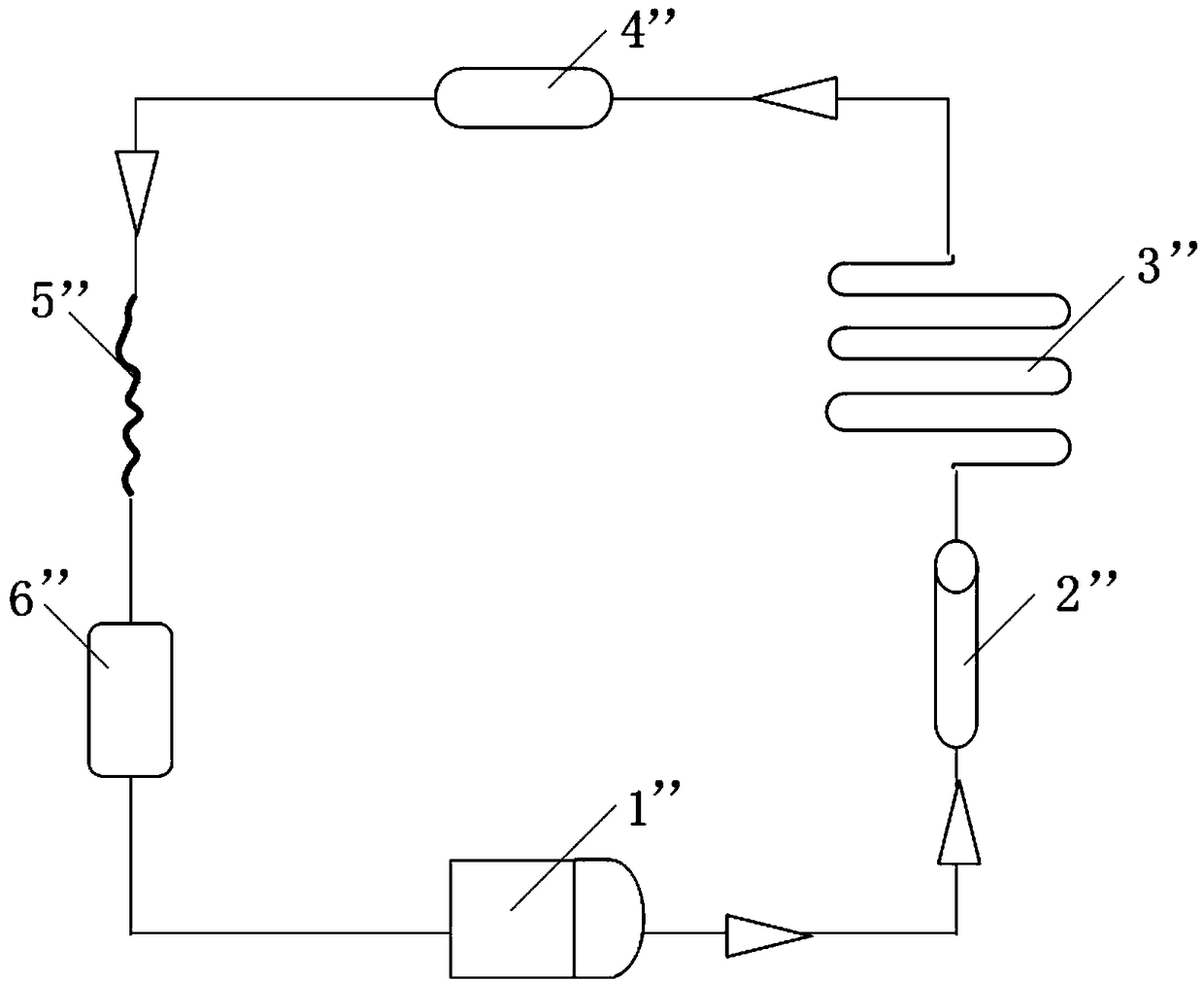
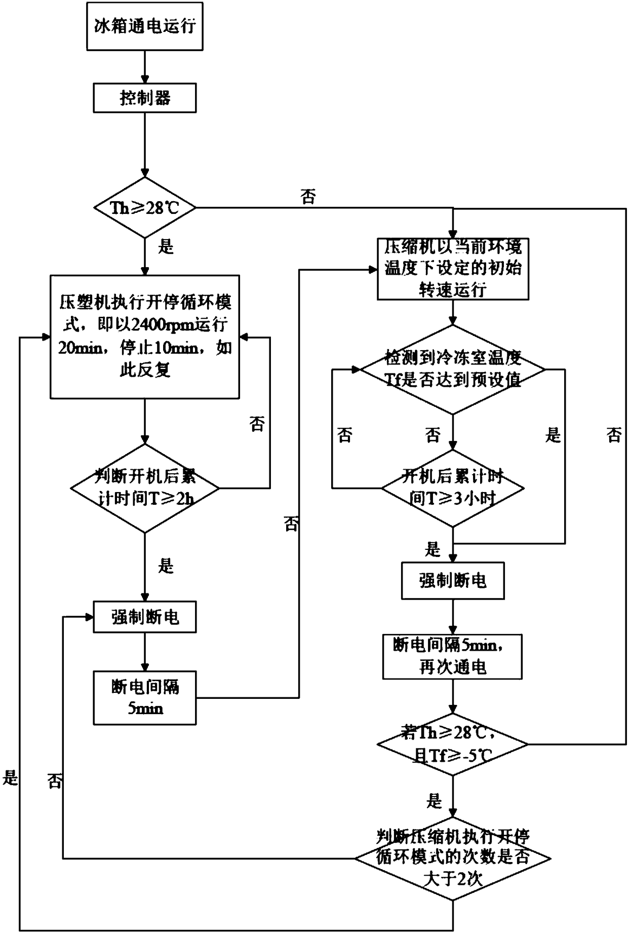
[0038] This embodiment is applied to adopt figure 2 In the refrigeration cycle system where the pipeline of the refrigerator integrated embedded condenser is located, a refrigerator compressor control method is provided in this embodiment, which is applied to the compressor 1" of the frequency conversion air-cooled refrigerator. It is mainly for the refrigerant ( Refrigerant) first flows through the anti-condensation pipe 2" and then flows through the integrated embedded condenser 3" inverter air-cooled refrigerator. By optimizing the control program of the inverter compressor, the temperature on the surface of the beam or vertical beam of the refrigerator at the initial stage of power-on is reduced. problems, thereby improving user experience and reducing the risk of the freezer door seal being so...


PUM


Abstract

The invention relates to the technical field of refrigerator control, and discloses a refrigerator compressor control method. The refrigerator compressor control method comprises the steps that a compressor is powered on, and a starting-stopping cycle mode is executed, and is kept for the first preset time; the starting-stopping cycle mode is that the compressor runs repeatedly in the state of running at a first preset rotating speed for the first preset time within the first preset time, and then stopping running for a second preset time; and the compressor runs at the initial rotating speedset at the current environment temperature. According to the control method, the problem that the temperature of the surface of a vertical beam or a middle beam is relatively high in the early stage of electrifying work of the refrigerator compressor is solved.

Description

technical field [0001] The invention relates to the technical field of refrigerator control, in particular to a method for controlling a refrigerator compressor. Background technique [0002] In the existing technology, such as figure 1 As shown, the condenser of the refrigerator mostly uses a split embedded condenser, that is, at the high-pressure end of the refrigeration system, the refrigerant first passes through the left condenser 1' on one side of the side plate, then passes through the anti-condensation pipe 2', and then passes through the other The right condenser 3' of one side plate flows to the low-pressure end after capillary throttling, and the heat 4' will cause the temperature of the freezer beam or vertical beam 5' to be too high. [0003] like figure 2 In order to optimize the assembly process and improve the welding efficiency, a scheme has emerged to replace the split embedded condenser with an integrated embedded condenser 3", which not only reduces so...

Claims


Application Information

Patent Timeline
Patent Type & Authority Applications(China)
IPC IPC(8): F25D29/00
CPCF25D29/00F25D2600/02F25D2600/06
Inventor 肖祥顺王锬棵闵龙张伟罗金兆文坚
Owner NANJING CHUANGWEI HOUSEHOLD ELECTRONICS APPLIANCES LTD
Why Eureka
Try Eureka