Supercavitation projectile regarding surface controlling drag reduction

A surface control and supercavitation technology, which is applied in the direction of projectiles, offensive equipment, weapon types, etc., can solve the problems of difficult implementation, high detection requirements of tail bubble sensors, and narrow application range, etc., and achieve easy implementation and intelligentization The effect of a wide range of applications and a simple structure

Inactive Publication Date: 2018-06-19
NANJING UNIV OF SCI & TECH
View PDF1 Cites 7 Cited by
  • Summary
  • Abstract
  • Description
  • Claims
  • Application Information

AI Technical Summary

Problems solved by technology

This method has too high requirements for the detection of the tail bubble

Method used


Image

  • Supercavitation projectile regarding surface controlling drag reduction
  • Supercavitation projectile regarding surface controlling drag reduction
  • Supercavitation projectile regarding surface controlling drag reduction

Examples


Embodiment Construction

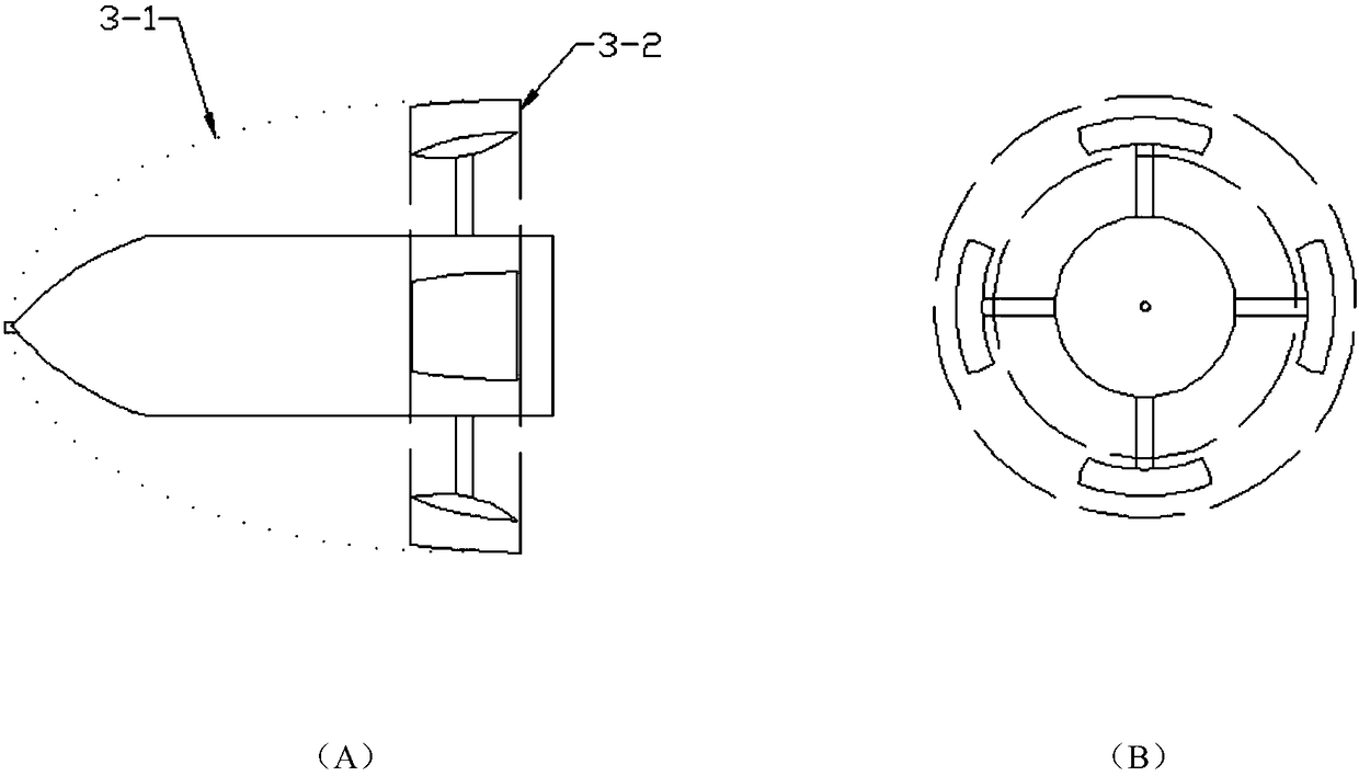
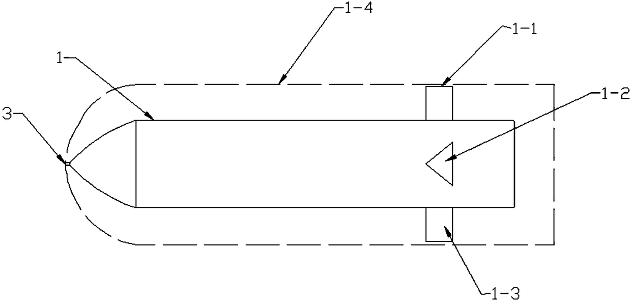
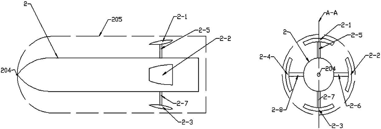
[0019] (1) The projectile body that forms an air cavity in the water, and the air cavity model is determined by the air-water boundary;

[0020] (2) The snowboard-type buffer connected with the projectile, the bottom of the snowboard-type buffer faces the air-water boundary of the air cavity;

[0021] (3) Drivers and controllers that change the position of the buffer based on the speed of the projectile and the air cavity model.

[0022] One disadvantage of the supercavitating projectile designed in the prior art is that the tail fin is easy to touch the air-water boundary, which increases the water resistance of the projectile's movement. Another disadvantage is that because the position of the tail fin is fixed, it cannot adapt to the change of the cavity shape caused by the change of the projectile speed.

[0023] The supercavitating underwater projectile designed by the present invention can maintain stability in the air cavity without the above-mentioned disadvantages. The tail ...


PUM


Abstract

The invention discloses a supercavitation projectile regarding surface controlling drag reduction. The supercavitation projectile regarding surface controlling drag reduction comprises a projectile body, buffers, a brace rod, a cavitation device, a sensor, a controller and a driver; the sensor for sensing the projectile speed is installed at the front end of the middle portion of the projectile body; the controller is installed in the projectile body, and receives information from the sensor and emits a control instruction; the driver is installed at the rear end of the projectile body and responds to the command of the controller to adjust the telescopic positions of the buffers; and the four buffers are uniformly distributed on the driver at the tail end of the projectile body. The supercavitation projectile can be kept stable in a gas cavity, and is simple in structure, easy to achieve and wider in intelligent application range.

Description

Technical field [0001] The invention relates to the field of underwater projectiles, in particular to a supercavitating projectile for surface control and drag reduction, which improves the surface structure of the projectile and realizes the purpose of drag reduction. Background technique [0002] When the underwater vehicle moves at a high speed, it will produce an empty cannon phenomenon under certain conditions. The empty cannon phenomenon usually refers to the low-pressure area of ​​the liquid flow field. When the liquid flow pressure reaches the saturated vapor pressure of the liquid, the liquid will vaporize to form "cavitation". Generally speaking, for an underwater vehicle surrounded by a flow field, when the length of the generated cavity is less than the length of the vehicle, it is called a partial cavitation; and when the length of the generated cavity reaches or exceeds the length of the vehicle, it is called Supercavitation. The "cavitation" makes the projectile ...

Claims


Application Information

Patent Timeline
IPC IPC(8): F42B10/38
CPCF42B10/38
Inventor 赵子杰张成龙江代文
Owner NANJING UNIV OF SCI & TECH
Why Eureka
Try Eureka