Testing method and device for resonant frequency of large generator housing

A test method and generator technology, applied in the direction of measuring resonance frequency, measuring device, measuring ultrasonic/sonic wave/infrasonic wave, etc., can solve the problems of high test cost, complex structure, large generator volume, etc., and achieve good economic benefits, test The method is simple and practical

Inactive Publication Date: 2018-06-19
ELECTRIC POWER RES INST OF STATE GRID ZHEJIANG ELECTRIC POWER COMAPNY +2
View PDF4 Cites 2 Cited by
  • Summary
  • Abstract
  • Description
  • Claims
  • Application Information

AI Technical Summary

Problems solved by technology

[0003] At present, the test method for the resonance frequency of the generator casing is mainly the modal method, but due to the l...

Method used


Image

  • Testing method and device for resonant frequency of large generator housing
  • Testing method and device for resonant frequency of large generator housing
  • Testing method and device for resonant frequency of large generator housing

Examples


Embodiment 1

[0029] This embodiment is a method for testing resonance of a large generator casing, and the specific test steps are described in detail as follows:

[0030] (1) Variable speed vibration test of generator shell

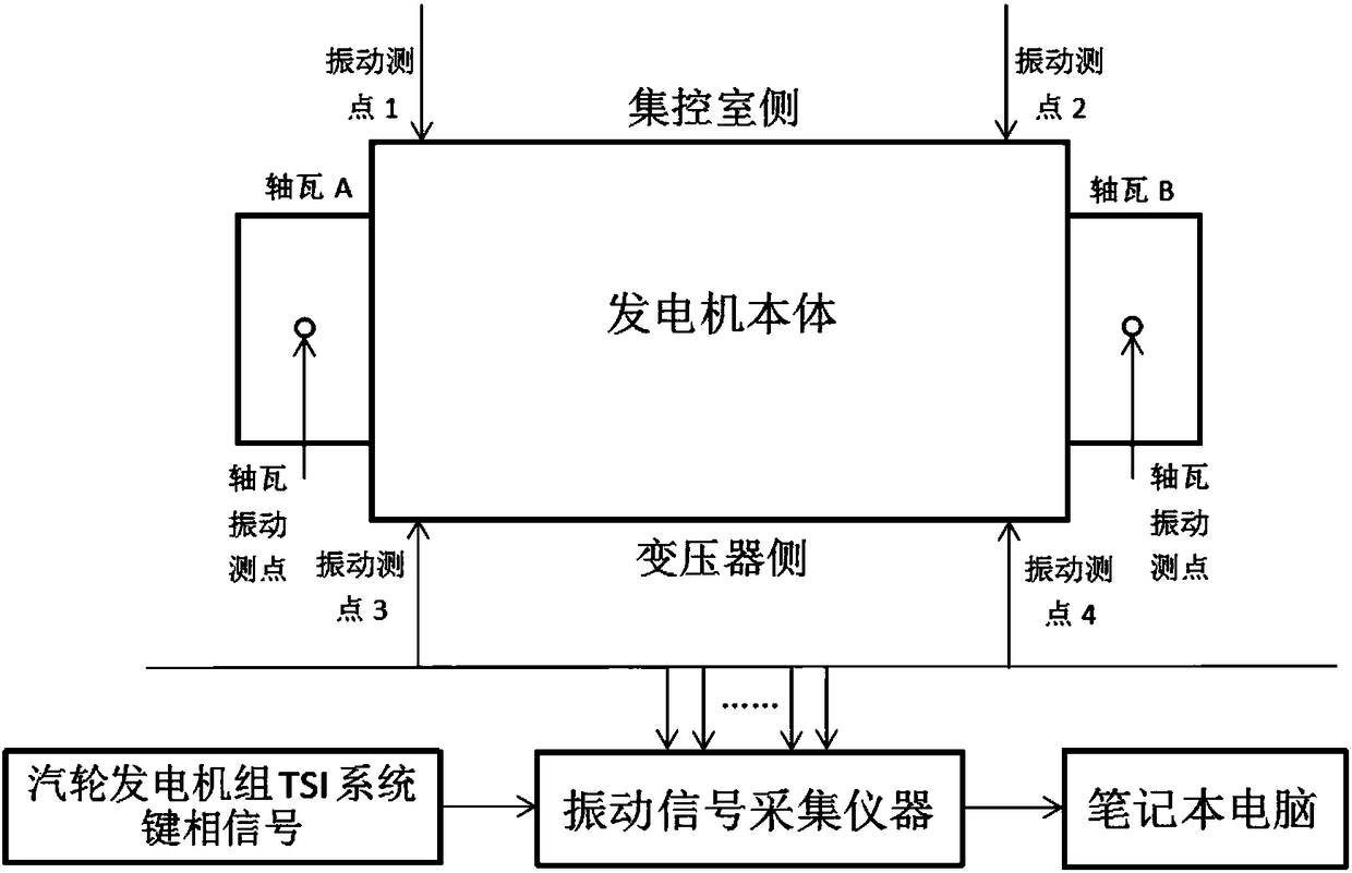
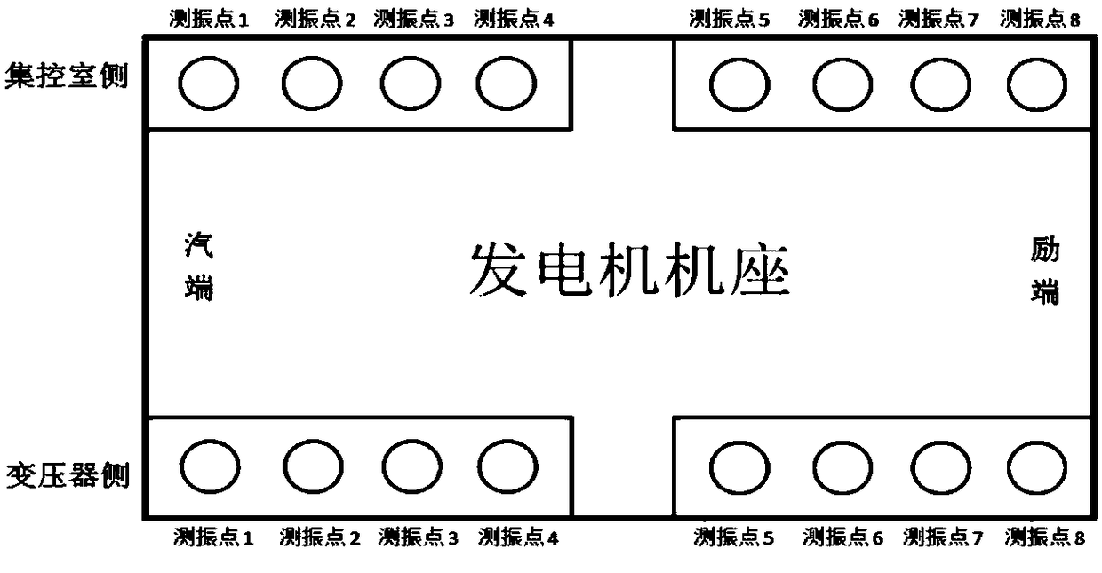
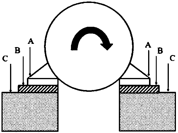
[0031] According to the on-site generator housing structure, the arrangement of the vibration sensor installed on the generator housing, see Figure 1-3 . The generator casing vibration is tested during the variable speed test and overspeed test of the unit.

[0032] (2) Calculation of resonance frequency and other parameters of generator casing

[0033] According to the vibration Bode diagram of the generator shell during the variable speed and overspeed test of the unit (see Figure 4 ), the resonance speed n of the generator casing is obtained i , Resonance frequency f c 、Resonance avoidance coefficient Ω i Use calculation formula:

[0034] f c = N i / 60 (1)

[0035] Ω i =|f c ﹣50| / 50 (2)

[0036] Where n i The unit is r / min; f c The unit is Hz; Ω i The unit is %.

[0037] Th...

Embodiment 2

[0046] This embodiment provides a resonance test device for a large generator housing, which includes:

[0047] Vibration data test unit: connect the key phase signal in the vibration monitoring system of the turbo-generator set and the vibration sensors installed in different parts of the generator shell to the vibration signal collector to test the vibration data during the speed change of the unit;

[0048] Bode diagram drawing unit: draw the Bode diagram of the generator shell vibration according to the vibration data;

[0049] Parameter calculation unit: Determine the resonance speed n of the generator stator housing according to the Bode diagram i , And calculate the resonance frequency f of the generator stator housing c 、Resonance avoidance coefficient Ω i , Resonance quality factor Q and damping coefficient ζ;

[0050] Resonance phenomenon judgment unit: when resonance avoidance coefficient Ω i <10% and damping coefficient ζ <2%, it is judged that there is a mechanical resonan...


PUM


Abstract

The invention discloses a testing method and device for the resonant frequency of a large generator housing. At present, a conventional testing method for the resonant frequency of a generator housingmainly is a modal method. Objectively speaking, however, a more accurate and easier testing method is needed since a generator is large in size, complicated in structure or the like and the testing cost is high. The technical scheme adopted by the invention is as follows: the method includes the steps of testing vibration of a generator housing in a condition of the variable speed of a set, drawing a corresponding Bode diagram, obtaining the resonant rotating speed of the generator housing, and calculating the resonant frequency, resonant aversion coefficients and resonant quality factors; and on the basis of the above step, further identifying faults such as bearing unevenness or stripping of a generator through vibration situations of end caps on the two sides of the on-site generator and supports on the two sides of the on-site generator, and thus providing reference for fault diagnosis of strong vibration of the generator housing. The testing method is easy and practical and has good economic benefits.

Description

Technical field [0001] The invention relates to the field of fault diagnosis of abnormal vibration of a large generator, in particular to a method and a device for testing the resonance frequency of the generator based on the characteristics of the vibration of the generator casing changing with the speed. Background technique [0002] With the development of generators in the direction of high parameters and large capacity, more stringent requirements are put forward for the laying of gaskets under the stator foot of the generator during installation. However, due to factors such as the foundation settlement of the generator set and the installation quality, the mechanical resonance of the generator stator housing, especially when the resonance frequency is close to 50 Hz, has a serious impact on safe and stable operation. In the large-scale generator stator housing vibration failure, the generator housing resonance has a higher probability. Therefore, determining the resonance...

Claims


Application Information

Patent Timeline
IPC IPC(8): G01H13/00
Inventor 李卫军吴文健应光耀张宝马思聪蔡文方
Owner ELECTRIC POWER RES INST OF STATE GRID ZHEJIANG ELECTRIC POWER COMAPNY
Why Eureka
Try Eureka