
Rotor target micro Doppler detection method based on cumulative equivalent three-point method

A micro-Doppler and detection method technology, applied in the field of target detection and recognition, can solve the problems of inability to directly extract micro-Doppler features, decrease in frequency domain resolution, broaden Doppler spectrum, etc., and achieve improved micro-Doppler The effect of feature extraction ability

Active Publication Date: 2018-06-19
SHANDONG INST OF AEROSPACE ELECTRONICS TECH
View PDF4 Cites 5 Cited by
  • Summary
  • Abstract
  • Description
  • Claims
  • Application Information

AI Technical Summary

Problems solved by technology

[0005] At present, most of the methods for estimating the micro-motion parameters of the micro-moving target are based on the assumption that the observation time is at least longer than one target rotation period, but in practical applications, when the radar is working in the scanning mode, the antenna must Scan the coverage area, where the beam dwell time is usually less than one target rotation period
This results in broadening of the Doppler spectrum and loss of resolution in the frequency domain, from which micro-Doppler features cannot be directly extracted
In response to this situation, T. Thayaparan et al. proposed a method for estimating micro-Doppler parameters of vibration targets based on part-period data—the three-point method. Domestic Xidian has also done applied research in this area, but this method generally It is still required that the time for the radar beam to illuminate the target is not less than 1 / 4 of the rotation period of the rotor target blade. When the irradiation time is too short, the parameter estimation error is too large due to the step size being too low
[0006] Therefore, there is no related research on the method of extracting target micro-Doppler features from the micro-scale periodic data obtained by high-resolution radar scanning of slow-rotating rotor targets.

Method used


Image

  • Rotor target micro Doppler detection method based on cumulative equivalent three-point method
  • Rotor target micro Doppler detection method based on cumulative equivalent three-point method
  • Rotor target micro Doppler detection method based on cumulative equivalent three-point method

Examples


Embodiment Construction

[0037] The present invention will be described in detail below with reference to the accompanying drawings and examples.

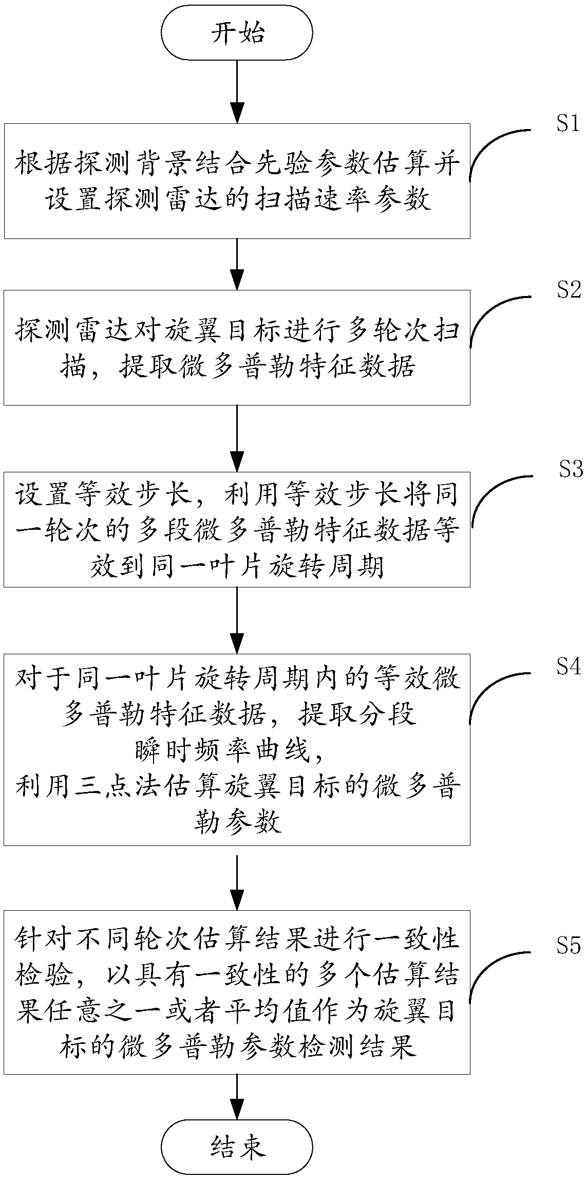
[0038] figure 1 It shows the rotor target micro-Doppler detection method based on the cumulative equivalent three-point method provided by the embodiment of the present invention, as figure 1 As shown, the method includes the following steps:

[0039] S1. Estimating and setting the scanning rate parameters of the detection radar according to the detection background and prior parameters.

[0040] The detection background in the embodiment of the present invention is the detection background applied by the method of the present invention, and the detection background includes the following three aspects:

[0041] 1) The maximum scan period of the detection radar does not exceed the set scan period threshold. In this embodiment, the set scan period threshold is 30s.

[0042] 2) The longest single irradiation time of the detection radar to the rotor targe...


PUM


Abstract

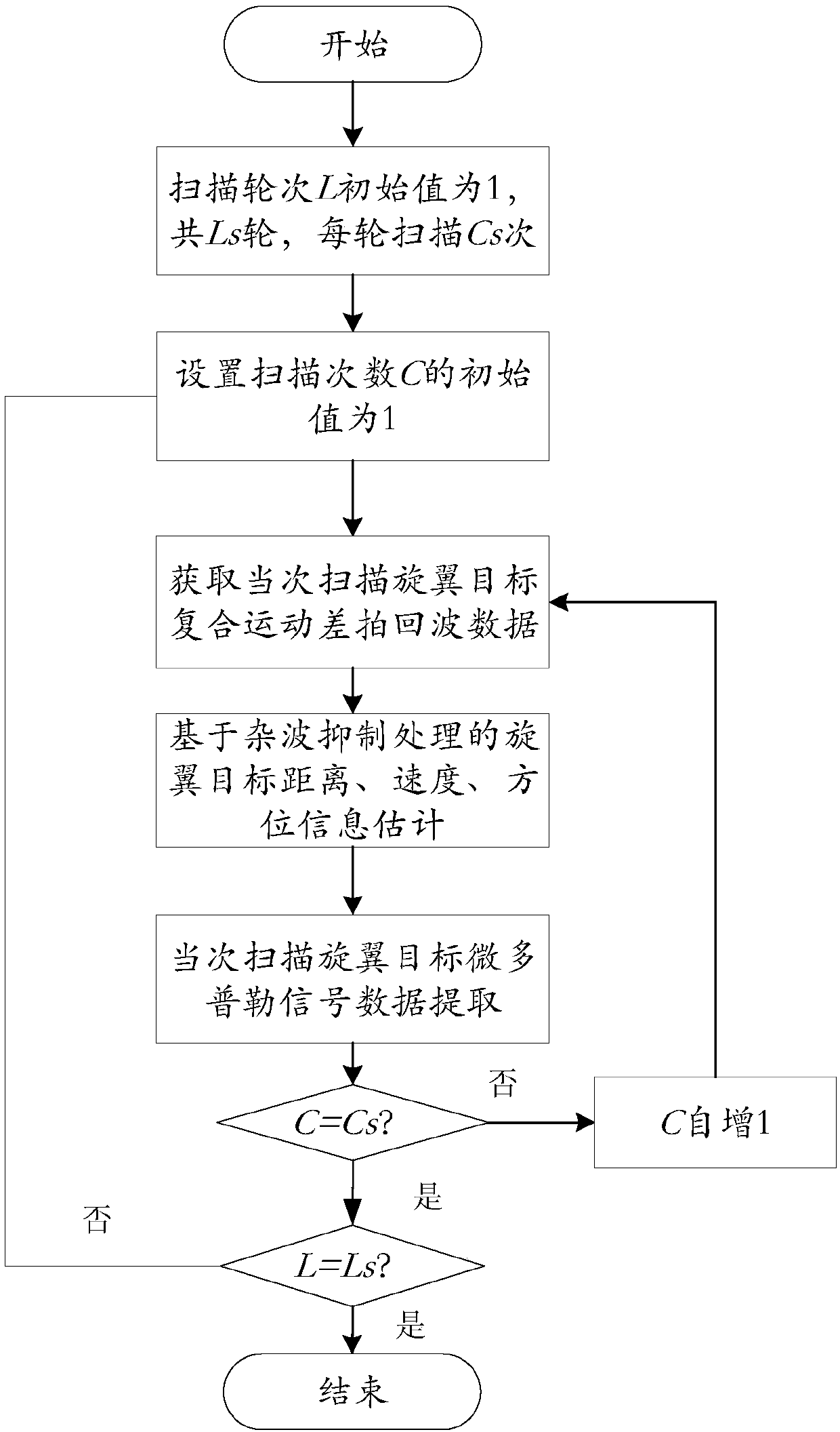
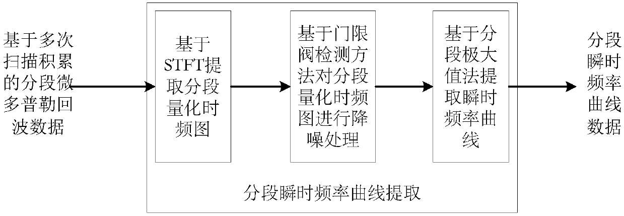
The invention discloses a rotor target micro Doppler detection method based on a cumulative equivalent three-point method, which can improve the ability of extracting micro Doppler characteristics ofa slow-rotation rotor target by a high resolution radar. The method particularly comprises the following steps: based on a detection background and prior parameters, a scanning rate parameter of a detection radar is estimated and set; the detection radar carries out multiple turns of scanning on the rotor target, and in each turn, continuous Cs times of scanning are carried out to extract Dopplercharacteristic data and a piecewise instantaneous frequency curve; an equivalent step length is used to enabling Cs sections of micro Doppler characteristic data obtained by Cs times of scanning in each turn to be equivalent to the rotation period of the same leaf; in the same turn, according to the piecewise instantaneous frequency curve, a three-point method is used to estimate the micro Dopplerparameters of the rotor target. Any one or the mean of the micro Doppler parameters of the rotor target with consistency obtained and estimated in multiple turns is used as the micro Doppler parameter detection result for the rotor target.

Description

technical field [0001] The invention relates to the technical field of target detection and recognition, in particular to a rotor target micro-Doppler detection method based on the cumulative equivalent three-point method. Background technique [0002] The micro-Doppler effect is a more detailed exploration of the echo signal changes caused by the movement of the target. It is known that the frequency modulation of the echo signal by the target accompanied by micro-motions such as vibration and rotation is called the micro-Doppler effect. The target characteristic extracted based on the micro-Doppler effect is the micro-Doppler characteristic. Since the concept of the micro-Doppler effect was put forward to the present, its application fields have involved multi-dimensional detection and identification of space, air and ground targets. [0003] Modern warfare has developed into an all-round combat mode of land, sea and air, so air combat has attracted more and more attentio...

Claims


Application Information

Patent Timeline
Patent Type & Authority Applications(China)
IPC IPC(8): G01S13/88G01S13/50
CPCG01S13/505G01S13/88
Inventor 张春红宋光磊周长青张峰会魏强张亚青王少刚
Owner SHANDONG INST OF AEROSPACE ELECTRONICS TECH
Learn More