No-blind-point catadioptric panoramic imager

A panoramic imaging and switchback technology, applied in the field of panoramic detection, can solve the problems of restricting the use and development of switchback panoramic lenses

Inactive Publication Date: 2018-06-19
CHANGCHUN INST OF OPTICS FINE MECHANICS & PHYSICS CHINESE ACAD OF SCI
View PDF5 Cites 10 Cited by
  • Summary
  • Abstract
  • Description
  • Claims
  • Application Information

AI Technical Summary

Problems solved by technology

This defect limits the use and development of the switchback type panoramic lens

Method used


Image

  • No-blind-point catadioptric panoramic imager
  • No-blind-point catadioptric panoramic imager
  • No-blind-point catadioptric panoramic imager

Examples


Embodiment Construction

[0027] In order to make the object, technical solution and advantages of the present invention clearer, the present invention will be further described in detail below in conjunction with the accompanying drawings and specific embodiments. It should be understood that the specific embodiments described here are only used to explain the present invention, but not to limit the present invention.

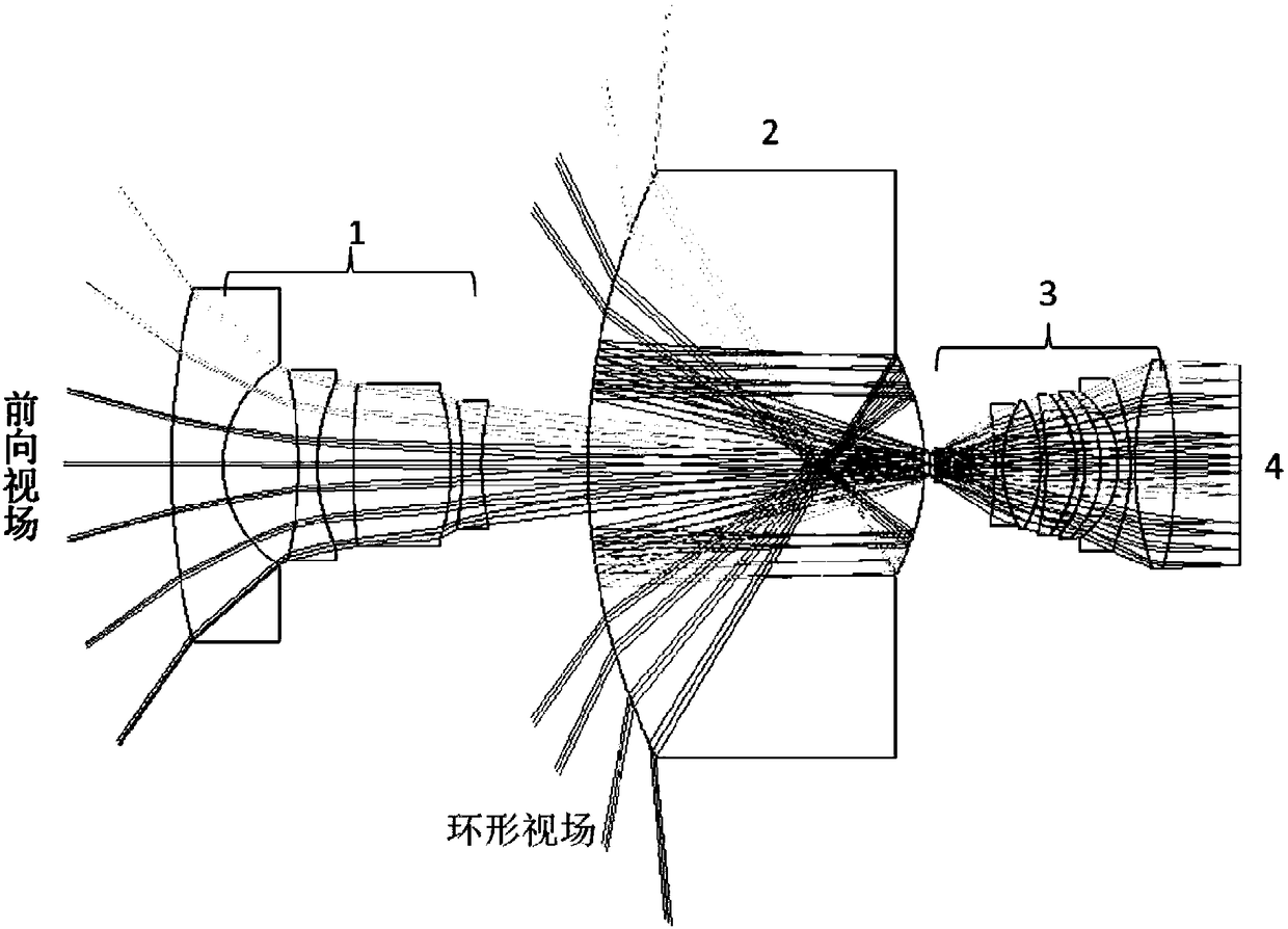
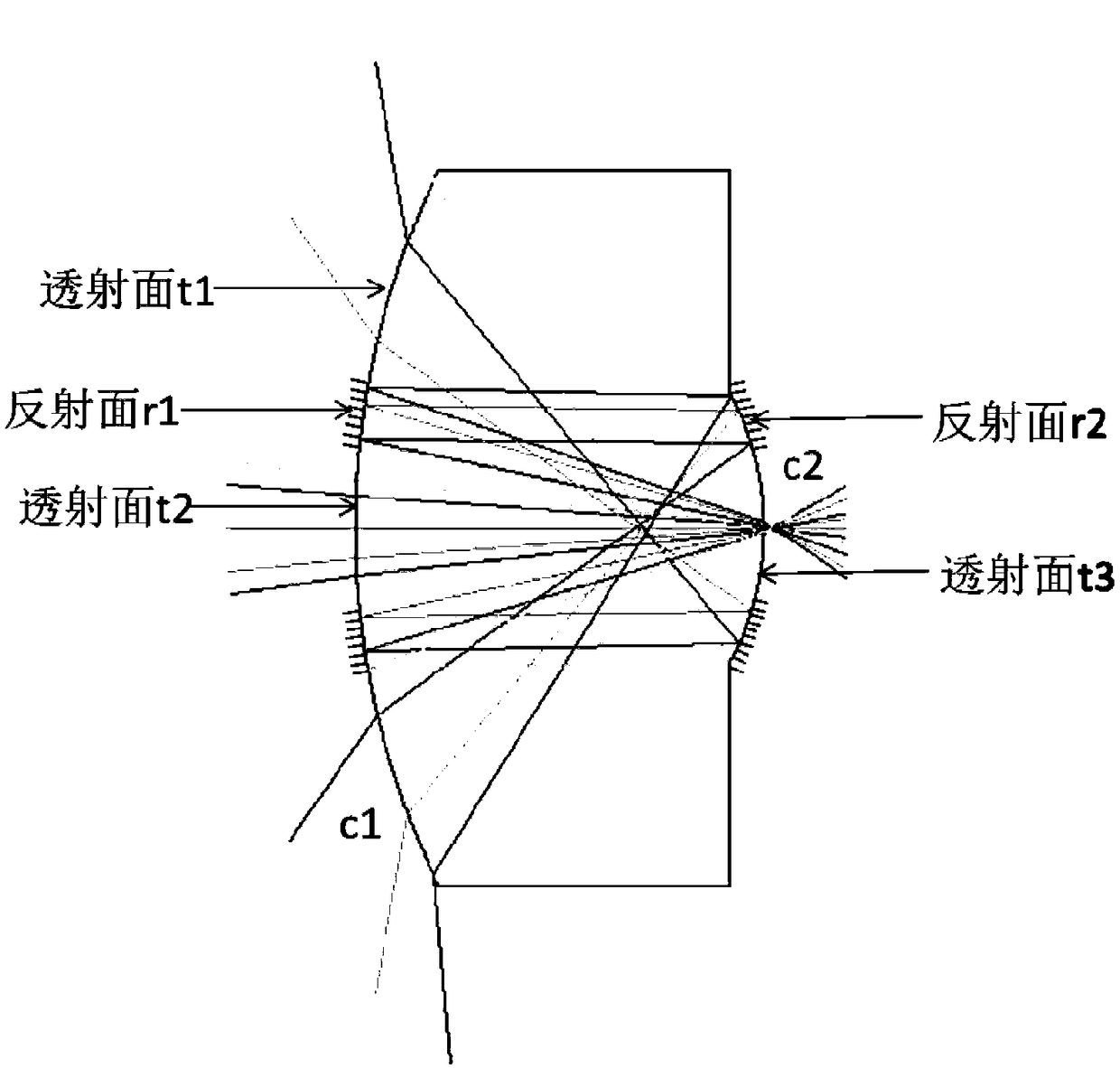
[0028] figure 1 The optical system of the blind-spot-free reentrant panoramic imager according to the embodiment of the present invention is shown. The optical system is composed of a front lens group 1, an annular folding mirror 2, a subsequent lens group 3 and an image plane detector 4.

[0029] The panoramic imager has two fields of view, a forward field of view and a circular field of view. In order to make the panoramic imager have no observation blind spots, the maximum half angle of field of view of the panoramic imager is equal to the minimum half angle of field of view of th...


PUM


Abstract

The invention discloses a no-blind-point catadioptric panoramic imager. The optical system comprises a forward field of view and an annular field of view and comprises a front lens set, an annular reflective mirror, a subsequent lens set and an image surface detector. The front lens set is used for receiving the light beams of the forward field of view. The annular reflective mirror is arranged after the front lens set and used for receiving the light beams of the annular field of view and transmitting the light beams of the forward field of view received by the front lens set. The subsequentlens set is arranged after the annular reflective mirror and used for performing aberration correction and relay image transformation on the light beams of the forward field of view and the annular field of view. The image surface detector is arranged after the subsequent lens set and used for imaging the light beams focused by the subsequent lens set. The forward field of view of the panoramic imager can greatly compensate the blind observation area of the common catadioptric large field-of-view imaging system so that the area utilization rate of the CCD detector can be enhanced and no-blind-area panoramic detection can be realized.

Description

technical field [0001] The invention relates to the field of panoramic detection, in particular to a turn-back panoramic imager without blind spots. Background technique [0002] Panoramic imaging technology is a technology for detecting and imaging all the scenes in the surrounding space. Panoramic imaging is divided into scanning panorama and direct-view panorama. Scanning panorama refers to the use of mechanical moving parts to drive the detection lens to rotate to complete the scanning of the surrounding space. Then use the image stitching technology to fuse the scanned images of different spaces together. Direct-view panorama refers to the one-time detection and imaging of all the scenes in the large field of view through some special large field of view lenses. [0003] Compared with scanning panoramic technology, direct-view panoramic technology has the advantages of compact size, no moving parts, no need for post-image fusion, and high imaging efficiency. The dir...

Claims


Application Information

Patent Timeline
Patent Type & Authority Applications(China)
IPC IPC(8): G03B37/02G01C11/02
CPCG03B37/02G01C11/025
Inventor 薛庆生王晓恒
Owner CHANGCHUN INST OF OPTICS FINE MECHANICS & PHYSICS CHINESE ACAD OF SCI
Why Eureka
Try Eureka