Special earthing trolley for integration of armored mid-set high-voltage switch cabinet electricity testing and earthing and using method thereof

A high-voltage switchgear and grounding trolley technology, applied in switchgear, switchgear settings, electrical components and other directions, can solve problems such as endangering personal safety, personal electric shock accidents, insufficient safety distance between personnel and live equipment, etc. Robust performance and safe results

Inactive Publication Date: 2018-06-19
STATE GRID CORP OF CHINA +1
5 Cites 0 Cited by

AI-Extracted Technical Summary

Problems solved by technology

[0003] However, when this type of switchgear is overhauling the busbar, according to safety technical measures, it is necessary to carry out power failure, power inspection, and grounding. ...

Method used

(2) grounding, the integrated special-purpose grounding trolley of putting in the armored high-voltage switchgear for electrical inspection and grounding is pushed into the armored middle-mounted high-voltage switchgear before carrying out the electric test, and the external grounding wire is reliably connected with the ground stake, After passing the electrical inspection, after confirming that the static contact of the switch cabinet ...

Abstract

The invention provides a special earthing trolley for integration of armored mid-set high-voltage switch cabinet electricity testing and earthing and a using method thereof. The special earthing trolley comprises an electricity testing device, a conductive rod, a moving contact, an upper earthing knife contact, an earthing wire, a bottom plate, a plurality of wheels, a trolley insulation panel, apush-pull insulation handle, an earthing knife with a control handle and an earthing wire hand driving device, wherein the trolley insulation panel is vertically arranged on the bottom plate; the lower end of the bottom plate is provided with the trolley insulation panel; the conductive rod is inserted in the trolley insulation panel and is arranged in parallel with the bottom plate; the earthingknife with a control handle and the earthing wire hand driving device are arranged on the trolley insulation panel; and the moving contact and the upper earthing knife contact are arranged on the conductive rod. The maintenance and operation work can be greatly facilitated, and the personal safety of personnel is ensured.

Application Domain

Switchgear arrangementsIndicating presence of current/voltage

Technology Topic

Image

  • Special earthing trolley for integration of armored mid-set high-voltage switch cabinet electricity testing and earthing and using method thereof
  • Special earthing trolley for integration of armored mid-set high-voltage switch cabinet electricity testing and earthing and using method thereof
  • Special earthing trolley for integration of armored mid-set high-voltage switch cabinet electricity testing and earthing and using method thereof

Examples

  • Experimental program(1)

Example Embodiment

[0023] Hereinafter, exemplary embodiments of the present disclosure will be described in more detail with reference to the accompanying drawings. Although the drawings show exemplary embodiments of the present disclosure, it should be understood that the present disclosure may be implemented in various forms and should not be limited by the embodiments set forth herein. On the contrary, these embodiments are provided to enable a more thorough understanding of the present disclosure and to fully convey the scope of the present disclosure to those skilled in the art.
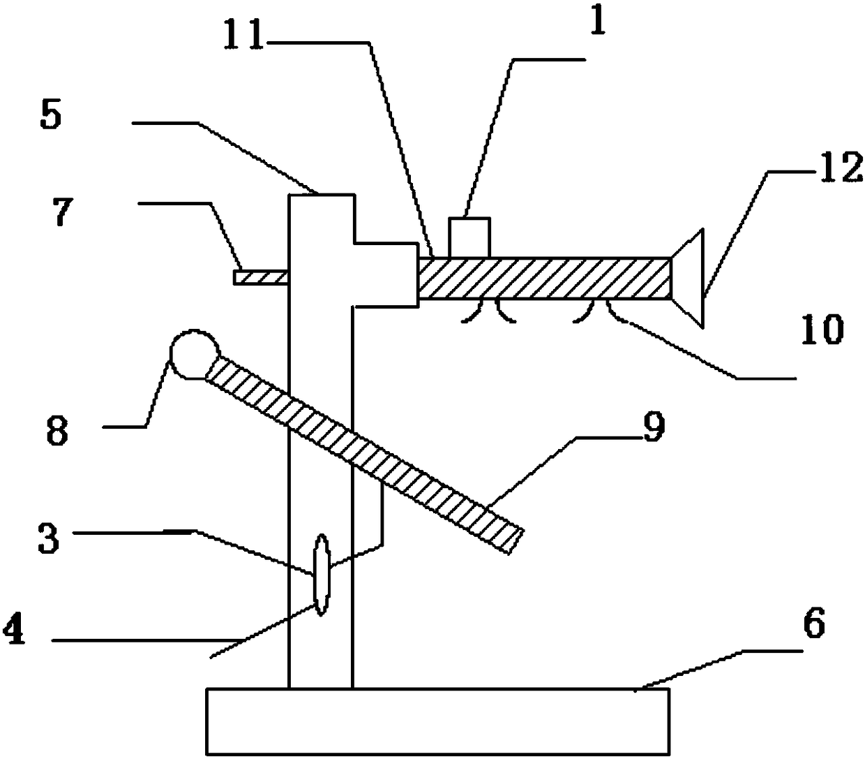
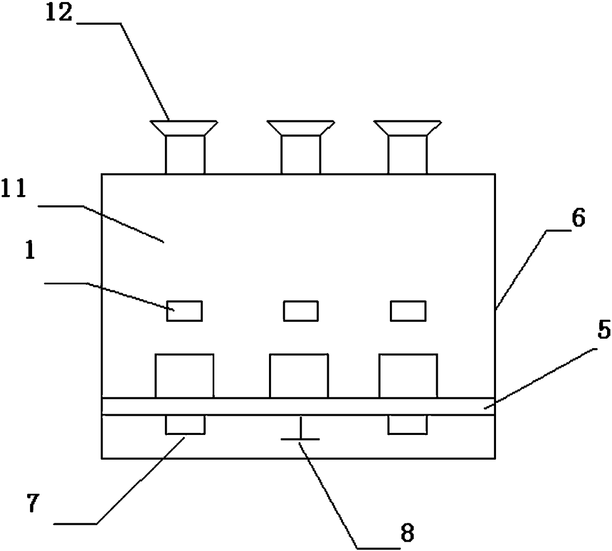
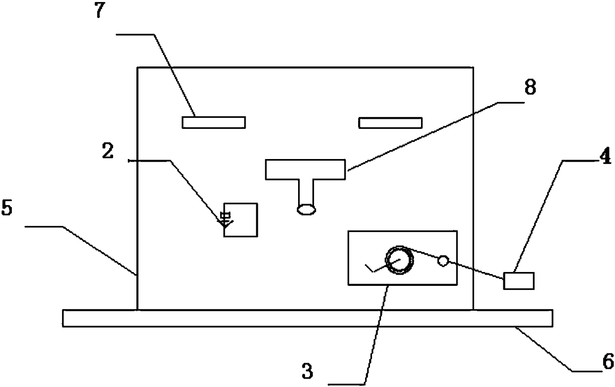
[0024] According to the embodiment of the present invention, a special grounding trolley for integrated electrical testing and grounding of armored central high-voltage switchgear is proposed, which includes electrical testing device 1, conductive rod 11, movable contact 12, upper grounding knife contact 10, and grounding Wire 4, bottom plate 6, several wheels, trolley insulation panel 5, push-pull insulation handle 7, grounding knife 9 with control handle 8 and grounding wire hand crank device 3. The trolley insulation panel is vertically arranged on the bottom plate, so A number of wheels are arranged at the lower end of the bottom plate, the conductive rods are inserted into the insulating panel of the trolley and arranged parallel to the bottom plate, and the grounding knife with the control handle and the grounding wire hand crank device are arranged on the insulating panel of the trolley, The movable contact and the upper grounding knife contact are arranged on the conductive rod, the electrical inspection device and the movable contact have three, and the three electrical inspection devices and the movable contact are evenly distributed on the conductive rod The push-pull insulated handle is arranged on the side of the junction between the conductive rod and the insulating panel of the trolley far away from the movable contact, and the three movable contacts are respectively an A-phase contact, a B-phase contact and a C-phase contact.
[0025] In another embodiment of the present invention, the grounding knife with a control handle further includes a first main rod, a second main rod, A-phase contact ground point 13, B-phase contact ground point 14 and C-phase contact The grounding point 15 of the B-phase contact is arranged on the first main pole of the grounding knife, and the grounding point of the A-phase contact and the grounding point of the C-phase contact are arranged on the second main pole of the grounding knife. The main rod and the second main rod are arranged perpendicular to each other. The second main rod is arranged parallel to the insulating panel of the trolley. The grounding knife with the control handle penetrates the insulating panel of the trolley. The control handle and the second main rod are respectively located on two sides of the insulating panel of the trolley. side.
[0026] Further, in other embodiments, the ground wire hand crank device is arranged on the side of the trolley insulation panel closer to the bottom plate, and the ground wire hand crank device drives the ground wire to realize mutual connection with the ground head and the ground knife . The control handle is an insulated handle for opening and closing of the ground knife, the insulating panel of the trolley is also provided with a ground knife opening and closing indicating device 2, and the ground wire is connected to the ground knife with a control handle. Preferably, the electroscope is a contact electroscope with a buzzer alarm function.
[0027] The present invention also provides a method for using a special grounding trolley for integrated electrical testing and grounding of an armored central high-voltage switchgear, which includes the following steps:
[0028] (1) Electric inspection, supporting the transportation trolley to drive the armored mid-mounted high-voltage switchgear electrical inspection and grounding integrated dedicated grounding trolley, and push the armored mid-mounted high-voltage switch cabinet electrical inspection and grounding integrated dedicated grounding trolley into the armored mid-mounted high voltage In the switch cabinet, make the moving contact and the static contact of the switch cabinet completely contact, and use the contact electroscope with the buzzer alarm function of the grounding trolley for electrical inspection;
[0029] (2) Grounding, push the armored mid-mounted high-voltage switchgear electrical inspection grounding integrated special grounding trolley into the armored mid-mounted high-voltage switchgear for electrical inspection, and reliably connect the external grounding wire to the grounding pile, and the electrical inspection is qualified Then, after confirming that the static contact of the switch cabinet has no power, pull the ground knife on the switch panel to open and close the insulated handle to switch on and off, and the ground knife with the control handle connected to the ground wire is connected to the upper movable contact conductive rod. The first main rod and the second main rod in the horizontal direction are respectively in contact with the A-phase contact, the B-phase contact and the C-phase contact to ensure reliable grounding;
[0030] (3) For the grounding wire, the grounding wire retractable device is used to retract the grounding wire by hand.
[0031] Preferably, in step (3), if electricity is found during electrical inspection, the grounding operation is prohibited. One of the special grounding trolley for electrical inspection and grounding integration of the drive armored middle high voltage switch cabinet and the armored middle high voltage switch cabinet A live locking device is installed between.
[0032] The beneficial technical effect achieved by the present invention is that the present invention can reliably complete the electrical inspection and grounding of the armored mid-mounted high-voltage switchgear after a power failure through the application of the special grounding trolley integrated for electrical testing and grounding of the armored mid-mounted high-voltage switchgear Working, the grounding wire has convenience, strong performance, low cost, high efficiency, and can ensure safety, convenience and reliability.
[0033] The above are only preferred specific embodiments of the present invention, but the protection scope of the present invention is not limited to this. Any person skilled in the art can easily think of changes or changes within the technical scope disclosed by the present invention. All replacements shall be covered within the protection scope of the present invention. Therefore, the protection scope of the present invention should be subject to the protection scope of the claims.

PUM

no PUM

Description & Claims & Application Information

We can also present the details of the Description, Claims and Application information to help users get a comprehensive understanding of the technical details of the patent, such as background art, summary of invention, brief description of drawings, description of embodiments, and other original content. On the other hand, users can also determine the specific scope of protection of the technology through the list of claims; as well as understand the changes in the life cycle of the technology with the presentation of the patent timeline. Login to view more.

Similar technology patents

Production method of filter screen supporting piece of dust collector

InactiveCN108841145AImprove hardness and fastnessStrong performancePolypropylenePolyimide
Owner:桐乡市富鸿塑业股份有限公司

Classification and recommendation of technical efficacy words

  • Strong performance
  • Low cost

Saloon car tyre surface

Owner:QINGDAO YELLOWSEA RUBBER

Embedded video playing device based on the dual processor

InactiveCN101009836AStrong performanceFacilitate reuse of hardware and software resourcesPulse modulation television signal transmissionDigital video signal modificationDsp processorHigh complexity
Owner:ZHEJIANG UNIV

Home-made automatic embedded computer system and display card driving method thereof

ActiveCN104360860AStrong performanceImprove human-computer interaction performance and graphics display and control performanceSpecific program execution arrangementsInstructions per secondGraphics
Owner:湖南长城科技信息有限公司 +1

System and method for transmitting wireless digital service signals via power transmission lines

ActiveUS7929940B1Reduce bandwidth requirementLow costInterconnection arrangementsWireless systems/telephoneElectric power transmissionBase transceiver station
Owner:NEXTEL COMMUNICATIONS

Nanowire structures comprising carbon

ActiveUS20070212538A1Low costImproved electrical connectivity and stabilityElectric discharge heatingFuel cells groupingNanometreMembrane configuration
Owner:ONED MATERIAL INC
Why Eureka
Try Eureka