Hinging type wire tightening clamp

A technology of tightening clamps and hinged plates, applied in the installation of electrical components, cables, overhead installations, etc., can solve the problems of low efficiency, cable overheating, randomness, etc., and achieve convenient installation and disassembly, convenient operation, and convenient operation Effect

Pending Publication Date: 2018-06-19
GUANGZHOU PANYU CABLE WORKS
View PDF0 Cites 6 Cited by
  • Summary
  • Abstract
  • Description
  • Claims
  • Application Information

AI Technical Summary

Problems solved by technology

[0002] Pin (column) insulators are devices used to support cables, generally used for high-voltage cables, such as figure 1 , 2 As shown, both pin insulators and post insulators are provided with top slots and annular side slots, and pin (post) insulators are fixed on street yard supports or buildings. In traditional use, the cable is close to the top of the pin insulator. slots or side slots, and then bind the cables and pin insulators by binding wires. This method is inefficient, and there is no uniform standard for the binding method and the tightness of the binding. Long-term use will loosen or even loosen. The binding wire is usually made of aluminum wire and other metal wires, which are directly wound on the cable sheath, which will cause damage to the cable sheath, and easily cause the danger of overheating or even short-circuiting of the cable, and the insulated cable will contact the metal wire There is a potential leakage due to direct contact

Method used


Image

  • Hinging type wire tightening clamp
  • Hinging type wire tightening clamp
  • Hinging type wire tightening clamp

Examples


Embodiment Construction

[0025] In order to make the object, technical solution and advantages of the present invention clearer, the present invention will be further described in detail below in conjunction with the accompanying drawings and embodiments. It should be understood that the specific embodiments described here are only used to explain the present invention, not to limit the present invention.

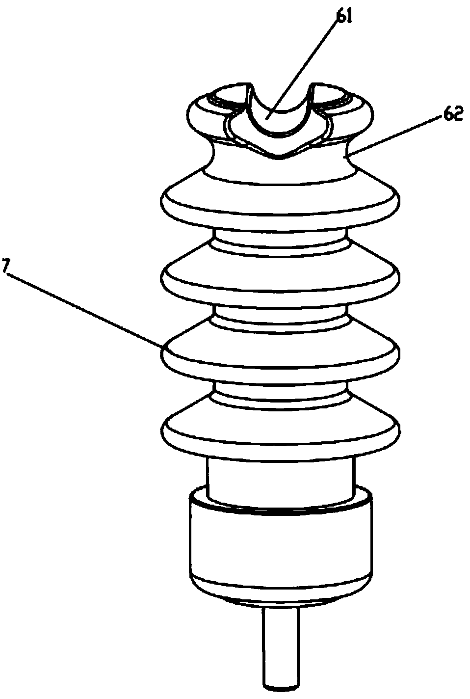
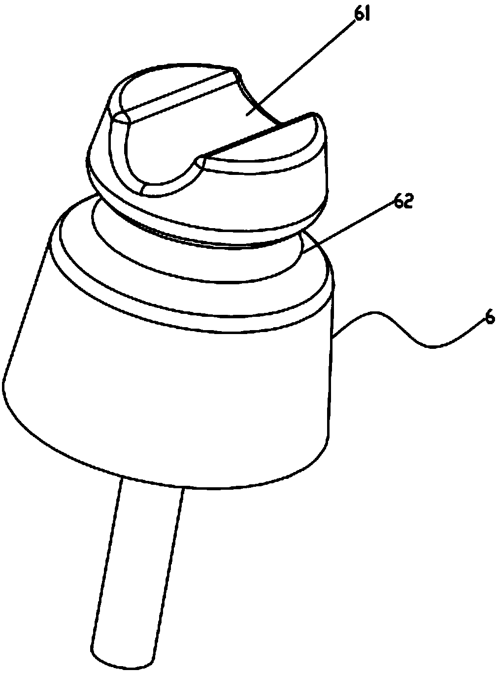
[0026] Such as Figure 1-2 As shown, both the pin insulator 6 and the post insulator 7 are provided with a top groove 61 and an annular side groove 62 .

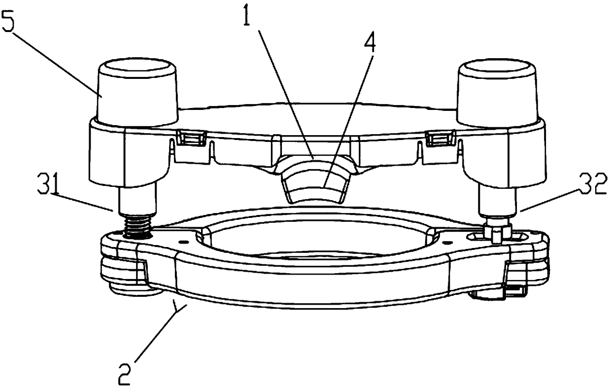
[0027] Such as Figure 3-6 As shown, the hinged tightening clamp includes a clamping plate 1 and a hinged plate assembly 2, the hinged plate assembly 2 includes a first clamping plate 21 and a second clamping plate 22 hinged at one end through a hinge shaft 311, the clamping plate 1 One end of the hinge plate assembly 2 is hinged through the first connecting piece 31, the first connecting piece 31 includes a hinge shaft 311 and a first threaded...


PUM


Abstract

The invention belongs to the cable installation field and relates to a hinging type wire tightening clamp. The hinging type wire tightening clamp comprises a wire pressing plate and a hinging plate assembly; the hinging plate assembly includes a first clamping plate and a second clamping plate; one end of the wire pressing plate is hinged to one end of the hinging plate assembly through a first connection component; the first connection component includes a hinging shaft and a first threaded sleeve which are in threaded connection with each other; the first threaded sleeve is hinged to the wire pressing plate; the other end of the wire pressing plate is detachably connected with the other end of the hinging plate assembly through a second connection component; the second connection component comprises a hanging rod and a second threaded sleeve which are in threaded connection with each other; the second threaded sleeve is hinged to the wire pressing plate; the hanging rod is provided with a non-circular hanging buckle; through holes are formed in the first clamping plate and the second clamping plate respectively; after the hanging buckle passes through the through holes, the hanging rod can be rotated, so that the hanging buckle can deviate from the second through hole so as to be hanged on the second clamping plate; the middle of the first clamping plate and the middle of thesecond clamping plate can be matched with each other, so that a clamping ring can be formed; and the wire pressing plate is provided with a wire pressing portion. The hinging type wire tightening clamp is convenient to install and disassemble, does not occupy space, and does not damage a cable.

Description

technical field [0001] The invention relates to the field of cable installation, in particular to a hinged clamp. Background technique [0002] Pin (column) insulators are devices used to support cables, generally used for high-voltage cables, such as figure 1 , 2 As shown, both pin insulators and post insulators are provided with top slots and annular side slots. Pin (post) insulators are fixed on street yard supports or buildings. In traditional use, the cable is close to the top of the pin insulator. slots or side slots, and then tie the cables and pin insulators to bind and fix them. This method is inefficient, and there is no uniform standard for the binding method and the tightness of the binding. Long-term use will loosen or even loosen. The binding wire is usually made of aluminum wire and other metal wires, which are directly wound on the cable sheath, which will cause damage to the cable sheath, and may easily cause dangers such as overheating of the cable or eve...

Claims


Application Information

Patent Timeline
Patent Type & Authority Applications(China)
IPC IPC(8): H02G7/05
CPCH02G7/056
Inventor 胡超强尤占山孙建吉覃丹陈雪儿卢广业张开拓王延发张仕欢郝燕邵源鹏程雪丽刘金勇
Owner GUANGZHOU PANYU CABLE WORKS
Why Eureka
Try Eureka