
Cooling device for die casting machine and cooling method thereof

A cooling device and die-casting machine technology, applied in the field of cooling devices, can solve the problems such as difficulty in setting the feeding rhythm and feeding cycle reasonably, the workpiece cooling time is not fixed, and the air cooling effect is not obvious, and the air cooling effect is obvious and the production The effect of high efficiency and increased cooling efficiency

Pending Publication Date: 2018-06-22
苏州康克莱自动化科技有限公司
View PDF5 Cites 2 Cited by
  • Summary
  • Abstract
  • Description
  • Claims
  • Application Information

AI Technical Summary

Problems solved by technology

[0002] Most of the existing air-cooling devices need to manually control the clamping time, or install air-cooling devices on both sides of the assembly line, so that the cooling is not uniform, the cooling time of the workpiece is not fixed, and the cooling efficiency is not high
The existing air-cooling device has potential safety hazards in production, the effect of air-cooling is not obvious, it is difficult to set the feeding cycle and feeding cycle reasonably, waste energy, and the cost is high

Method used


Image

  • Cooling device for die casting machine and cooling method thereof
  • Cooling device for die casting machine and cooling method thereof

Examples


Embodiment Construction

[0023] The technical solutions of the present invention will be described in detail below in conjunction with the accompanying drawings and preferred embodiments. However, the examples are merely exemplary and do not limit the scope of the present invention in any way. Those skilled in the art should understand that the details and forms of the scheme of the present invention can be modified or replaced without departing from the scope of the present invention, but these modifications and replacements all fall within the protection scope of the present invention.

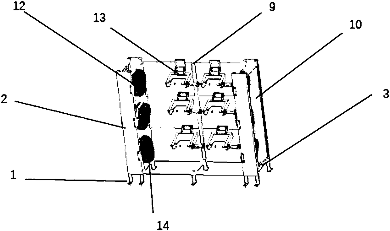
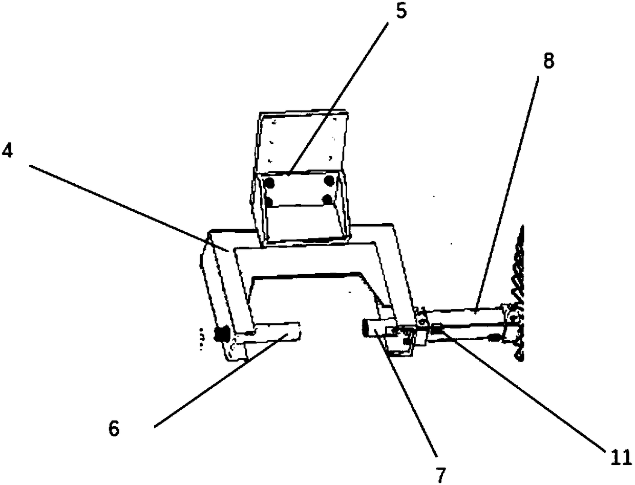
[0024] Such as figure 1 and figure 2 As shown, the present invention discloses a cooling device for a die-casting machine. The cooling device for a die-casting machine includes a cooling jaw 13, a cooling bracket 9, and an air-cooled fan group 12; the cooling jaw 13 includes a channel steel compartment 4, Workpiece fixing cylinder 8, collet 6 and jacking block 7; said workpiece fixing cylinder 8 is installed on t...


PUM


Abstract

The invention discloses a cooling device for a die casting machine and a cooling method thereof. The cooling device for the die casting machine is characterized by comprising a cooling clamping jaw, acooling bracket and an air cooling fan group, wherein the cooling clamping jaw comprises a channel steel compartment, a workpiece fixing air cylinder, a clamping head and a top block; the workpiece fixing air cylinder is arranged on the front end of the channel steel compartment; the top block is fixed to a piston rod of the workpiece fixing air cylinder and can horizontally move along with the piston rod of the workpiece fixing air cylinder; the clamping head is arranged on the other end of the channel steel compartment and can be engaged with the top block; and the cooling clamping jaw is fixed to the cooling bracket by a fixed block. According to the cooling device for the die casting machine, the production safety is guaranteed, the cooling efficiency is greatly improved, and the aircooling effect is obvious.

Description

technical field [0001] The invention relates to the technical field of a cooling device, in particular to a cooling device for a die-casting machine and a cooling method thereof. Background technique [0002] Most of the existing air-cooling devices need to manually control the clamping time, or install air-cooling devices on both sides of the assembly line, so that the cooling is not uniform, the cooling time of the workpiece is not fixed, and the cooling efficiency is not high. The existing air-cooling device has potential safety hazards in production, the air-cooling effect is not obvious, and it is difficult to set the feeding cycle and feeding cycle reasonably, which wastes energy and costs a lot. Contents of the invention [0003] The purpose of the present invention is to overcome the deficiencies in the prior art, solve the problems in the prior art, and provide a cooling device for a die-casting machine and a cooling method thereof, which not only ensure the safet...

Claims


Application Information

Patent Timeline
IPC IPC(8): B22D17/22
CPCB22D17/2218
Inventor 彭光军张丽
Owner 苏州康克莱自动化科技有限公司
Learn More