Clamp for machining

A kind of machining and fixture technology, applied in the direction of manufacturing tools, metal processing equipment, metal processing machinery parts, etc., can solve the problems of inaccurate processing accuracy, inaccurate drilling angle, difficult to adjust the processing angle, etc., to achieve a high degree of automation, Accurate clamping angle, correcting the effect of clamping angle

Active Publication Date: 2018-06-22
深圳市雄华光学有限公司
View PDF4 Cites 0 Cited by
  • Summary
  • Abstract
  • Description
  • Claims
  • Application Information

AI Technical Summary

Problems solved by technology

It can process planes and grooves, and can also process various curved surfaces, gears, etc. It is difficult to fix and clamp the cylindrical workpiece surface with a general fixture that is drilled on a CNC machine tool, and it is difficult to adjust the processing angle, resulting in inaccurate adjustment of the processing angle. , the drilling angle is not accurate, which cannot meet the needs of CNC machining, making the work of the staff more difficult, resulting in inaccurate machining accuracy or even difficult machining

Method used


Image

  • Clamp for machining
  • Clamp for machining
  • Clamp for machining

Examples


Embodiment Construction

[0019] A specific embodiment of the present invention will be described in detail below with reference to the accompanying drawings, but it should be understood that the protection scope of the present invention is not limited by the specific embodiment.

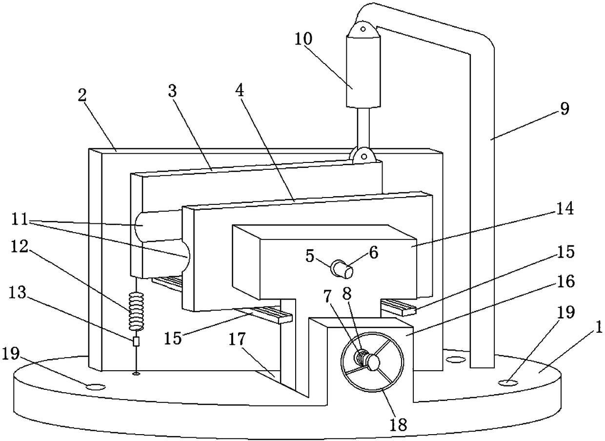
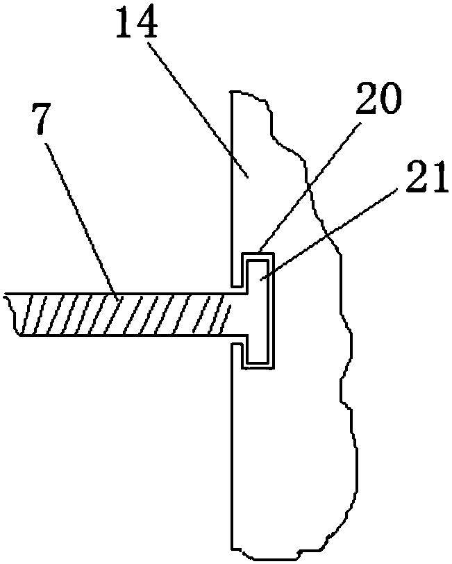
[0020] see figure 1 , figure 2 , the embodiment of the present invention provides a fixture for machining, including a fixed plate 1, a clamping baffle 2 is fixed on the fixed plate 1, and a clamping block 14 is also slidably connected to the fixed plate 1. Between the clamping baffle 2 and the clamping block 14 are provided a first clamping plate 3 and a second clamping plate 4 for clamping the machining shaft, wherein the first clamping plate 3 is fixed with a first clamping plate 3 . The rotating shaft, the first rotating shaft is inserted into the first through hole opened on the clamping baffle plate 2 , the second rotating shaft 6 is fixed on the second clamping card plate 4 , and the second rotating shaft 6 is inser...


PUM


Abstract

The invention provides a clamp for machining. A fixing plate of the clamp is fixedly provided with a holding baffle and connected with a holding block in a sliding mode. A first holding clamping plateand a second holding clamping plate for holding a machining shaft are arranged between the holding baffle and the holding block, and are in sliding connection through a guide rail. The fixing plate further comprises a base body with a threaded hole, a screw rod is connected in the threaded hole in a threaded mode, one end of the screw rod is hinged to the holding block, and the other end of the screw rod is provided with a hand cranking wheel. The left end of the first holding clamping plate is connected with the fixing plate sequentially through a spring and a tension sensor. The right end of the first holding clamping plate is connected with a force applying mechanism. The tension sensor is in signal connection with a microprocessor, and the microprocessor is further in signal connection with a storage module, a touch operation panel and the force applying mechanism. The tension of the spring is detected through the tension sensor, and the holding angle of the machined shaft can beaccurately and automatically determined according to the tension and holding angle correspondence relationship acquired in advance.

Description

technical field [0001] The present invention relates to the field of machining tools, in particular to a fixture for machining. Background technique [0002] The fixture is a device used to fix the processing object in the process of machinery manufacturing, so that it occupies the correct position to accept construction or inspection. In order to ensure the production quality of the product, when processing the workpiece on the machine tool, in order to make the surface of the workpiece meet the requirements of the drawing. According to the technical requirements of the size, geometry and mutual position accuracy with other surfaces, the workpiece must be positioned and clamped before processing, so as to produce qualified products. [0003] Milling machines mainly refer to machine tools that use milling cutters to process various surfaces of workpieces. Usually, the milling cutter mainly moves by rotation, and the movement of the workpiece and the milling cutter is the fe...

Claims


Application Information

Patent Timeline
IPC IPC(8): B23Q3/06B23Q17/00
CPCB23Q3/06B23Q17/005
Inventor 不公告发明人
Owner 深圳市雄华光学有限公司
Why Eureka
Try Eureka