
Multi-channel air suction mute cavity

A silent cavity and multi-channel technology, applied in the direction of liquid displacement machinery, variable displacement pump components, machines/engines, etc., to achieve the effects of reducing noise, increasing gas transmission coefficient, and improving energy efficiency ratio

Inactive Publication Date: 2018-06-22
胡雨思
View PDF0 Cites 0 Cited by
  • Summary
  • Abstract
  • Description
  • Claims
  • Application Information

AI Technical Summary

Problems solved by technology

[0003] The purpose of the present invention is to solve the contradictory problem between the noise and performance of the suction muffler cavity. It is necessary to make the suction muffler cavity have a good noise reduction function, and at the same time improve the suction efficiency of the compressor. A multi-channel suction muffler is designed. Gas quiet cavity

Method used


Image

  • Multi-channel air suction mute cavity
  • Multi-channel air suction mute cavity

Examples


example 1

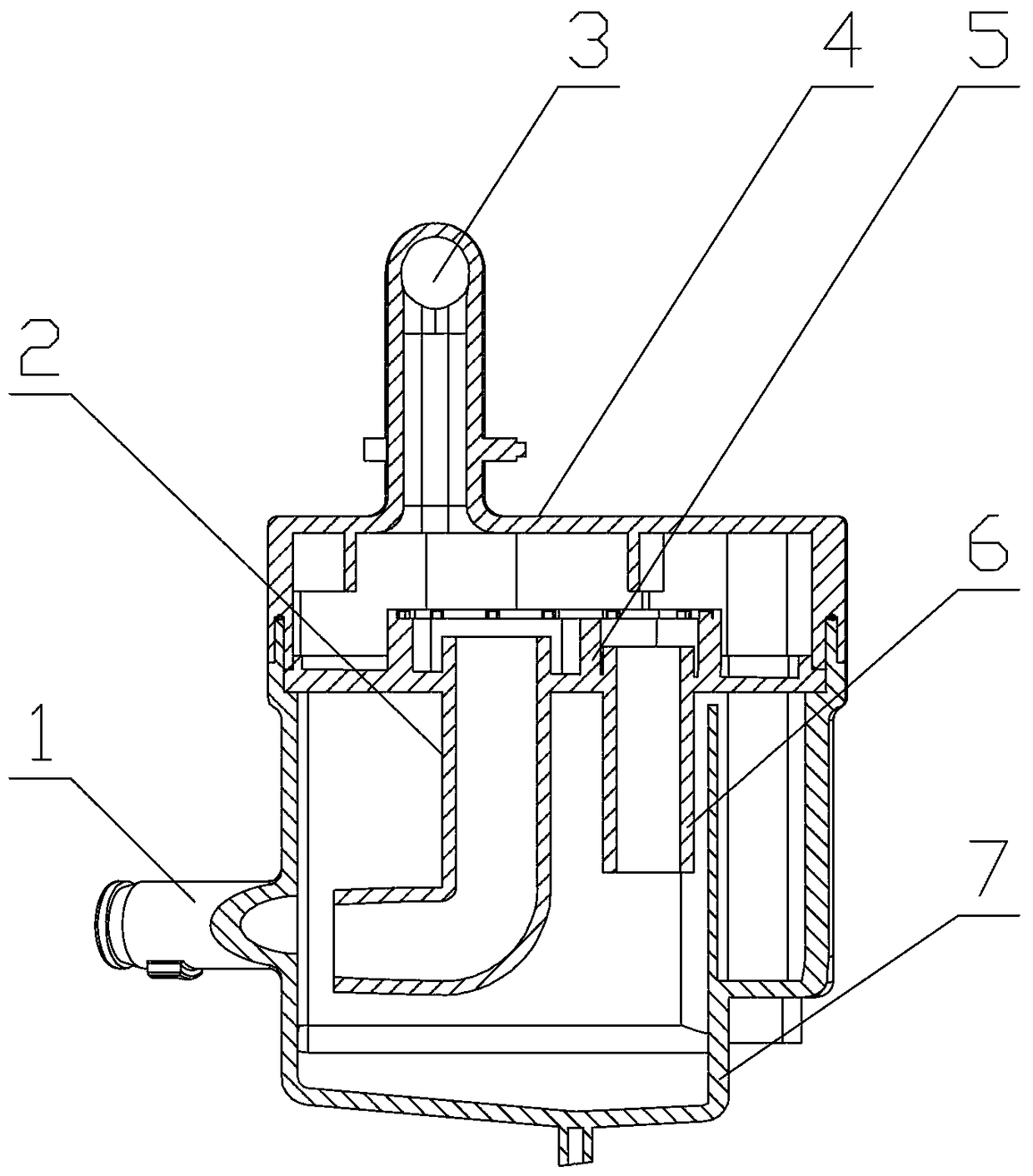
[0019] Example 1: see figure 1 , which is a direct suction double-communication pipe type suction muffler chamber, which includes an upper quiet room 4 and a lower quiet room 7 and a communication mechanism 5 installed between the two rooms, and the upper quiet room 4 is equipped with The air outlet 3 and the lower silent chamber 7 are provided with an air inlet 1, especially: a U-shaped main communication channel 2 and a secondary communication channel 6 are designed on the communication mechanism 5, and the inner diameter of the U-shaped main communication channel 2 is φ10-φ12mm , the specific option is φ8mm, the wall thickness is 4.5-5mm, the specific option is 1mm, the total length is 33-35mm, the specific option is 30mm; the inner diameter of the secondary communication channel 6 is φ8.5-φ10mm, the specific option is φ5mm, the wall thickness is 4.5 -5mm, specifically 2mm is optional, the total length is 26-30mm, specifically 16mm is optional. (The specific value of each ...

example 2

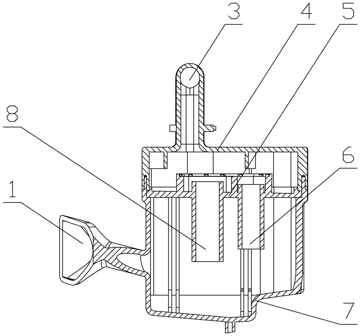
[0020] Example 2: see figure 2 , which is a semi-direct suction three-communication pipe-type suction muffler chamber, which consists of an upper quiet room 4, a lower quiet room 7 and a communication mechanism 5 installed between the two rooms, and there is a The air outlet 3, the lower silent room is provided with an air inlet 1, especially: a horizontal pipe, a vertical pipe type main communication channel 8 and two auxiliary communication channels 6 are designed on the communication mechanism 5 (two auxiliary communication channels 6 Front and back arrangement, one shown in the figure), the inner diameter of horizontal pipe and vertical pipe type main communication channel 8 is φ10mm, the wall thickness is 3mm, the total length is 20mm, and the inner diameter of two auxiliary communication channels 6 is φ4mm, and the wall thickness is 2mm , the total length of each secondary communication channel is 15mm.


PUM


Abstract

The invention relates to a refrigeration compressor component improvement technology and discloses a multi-channel air suction mute cavity. The multi-channel air suction mute cavity comprises an uppermute chamber, a lower mute chamber and a communicating mechanism, wherein the communicating mechanism is mounted between the two chambers. An air outlet is formed in the upper mute chamber, and an air inlet is formed in the lower mute chamber. The multi-channel air suction mute cavity is characterized in that the communicating mechanism is designed to be provided with a main communicating channeland multiple subsidiary communicating channels. According to the multi-channel air suction mute cavity, the communicating mechanism is additionally provided with a communicating pipe, so that noise at different frequency bands are reduced; and the energy efficiency ratio of a compressor can be increased, and the noise of the compressor can be reduced.

Description

technical field [0001] The invention relates to the component improvement technology of a refrigerating compressor, in particular to a multi-communicating pipe suction muffler cavity for a fully enclosed reciprocating piston refrigerating compressor. Background technique [0002] At present, in the fully enclosed refrigeration compressors used in refrigerators (freezers), the generally used suction muffler chamber is composed of an upper quiet room, a lower quiet room and a communication mechanism installed between the two rooms. In the traditional suction muffler chamber The connecting mechanism of the compressor is designed as a single connecting pipe structure, which is easy to design and manufacture. According to the displacement of the compressor, the appropriate diameter of the connecting pipe can be selected. In general, in order to achieve a higher energy efficiency ratio, a larger aperture will be selected appropriately. However, when the displacement of the compre...

Claims


Application Information

Patent Timeline
Patent Type & Authority Applications(China)
IPC IPC(8): F04B39/00
CPCF04B39/0055
Inventor 胡雨思
Owner 胡雨思
Learn More