
A method for manufacturing a suction valve plate of a reciprocating piston compressor

A suction valve plate, reciprocating piston technology, applied in the field of refrigeration compressors, can solve the problems of difficulty in further improving the COP of the compressor, large relative clearance, small gas transmission coefficient, etc., so as to improve the ability to resist fatigue damage and the clearance The effect of volume reduction and reliability improvement

Active Publication Date: 2015-10-28
WUHU ABAUR MECHANICAL & ELECTRICAL
View PDF3 Cites 1 Cited by
  • Summary
  • Abstract
  • Description
  • Claims
  • Application Information

AI Technical Summary

Problems solved by technology

[0005] In the piston compressor, when the piston runs to the outer dead center, the volume between the top surface of the piston and the bottom surface of the valve plate and the valve channel that is always connected with the cylinder form a clearance volume, and the ratio of the latter is due to the clearance volume There is always a part of the gas occupying the exhaust channel and cannot be discharged, which makes the relative clearance c larger, resulting in a smaller volume coefficient λv, and thus a smaller gas transmission coefficient, making it difficult to further improve the COP of the compressor

Method used


Image

  • A method for manufacturing a suction valve plate of a reciprocating piston compressor
  • A method for manufacturing a suction valve plate of a reciprocating piston compressor
  • A method for manufacturing a suction valve plate of a reciprocating piston compressor

Examples


Embodiment 1

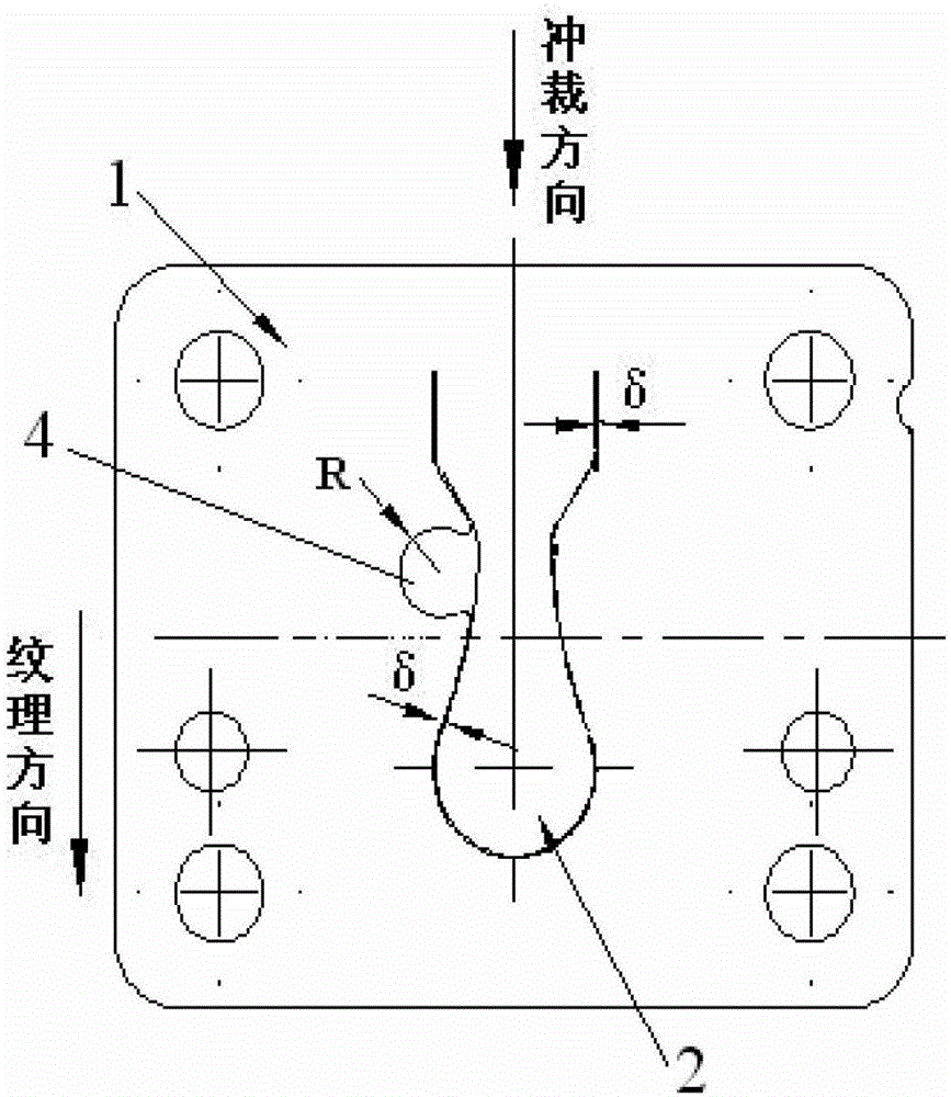
[0028] Such as figure 1 The structure of the present invention shown is a suction valve plate of a reciprocating piston compressor, which is used for a fully enclosed reciprocating piston refrigeration compressor, and is provided with a valve plate body 1, a suction valve reed 2 and an exhaust hole 4.

[0029] In order to solve the problems existing in the prior art and overcome its defects, realize the invention purpose of improving the gas transmission coefficient of the suction valve plate, improving the COP and compressor efficiency, and improving the reliability of the suction valve plate, the technical scheme adopted by the present invention is:

[0030] For the suction valve plate of the reciprocating piston compressor of the present invention, the gap between the suction valve reed 6 and the valve body 1 is δ≤0.4mm; the radius of the exhaust hole 4 is R3.

[0031] The longitudinal direction of the suction valve reed 2 is the punching direction, and the punching direct...

Embodiment 2

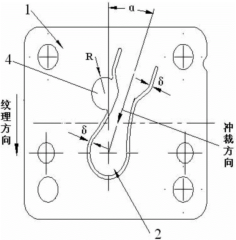
[0040] Such as figure 2 As shown, the punching direction in the first embodiment is changed to form this embodiment: that is, the included angle between the punching direction and the texture direction of the valve body 1 is 5°-20°. All the other technical solutions are the same as in Embodiment 1.

[0041] The material of the above-mentioned small gap suction valve plate of the present invention is Sandvik 20C carbon steel, and the reed position and the punching direction of the valve plate form an included angle of 5° to 20°. The same as in the first embodiment: the gap width of the suction valve plate is reduced from 0.4 to 0.5 mm in the prior art to 0.1 mm to 0.2 mm, even smaller than 0.1 mm; Air hole 4 is adjusted from R3.5 to R3.

[0042] Through design improvement, the relative clearance volume c=0.045 is reduced to c=0.03, the volume coefficient λv increases, the pressure coefficient λp increases due to the reduction of the relative clearance volume c and the increa...

Embodiment 3

[0046] The carbon steel strip Sandvik20C in Embodiment 1 or Embodiment 2 is replaced to form this embodiment, that is, the material of the above-mentioned suction valve plate is changed to spring steel strip 7C27Mo2. All the other technical solutions are the same as those in Embodiment 1 or Embodiment 2.

[0047]Martensitic stainless steel 7C27Mo2 has extremely high fatigue strength under bending and impact stress, and high residual compressive stress on the surface. This determines that the tensile stress on the punching edge of the valve plate is changed into compressive stress after punching and rolling, which greatly enhances the fatigue strength of the valve plate and the straightness of the valve plate; the fatigue strength of the valve plate and the After the flatness of the valve is increased, the lift of the valve plate can be increased, the airflow loss of the valve plate can be reduced, the efficiency of the compressor can be improved, the air transmission coefficie...


PUM


Abstract

The invention discloses a method for manufacturing an air suction valve plate of a reciprocating piston compressor. The air suction valve plate is used for fully sealing the reciprocating piston compressor. The method is characterized in that the air suction valve plate is subjected to roll-polishing after the air suction valve plate is punched, the overall dimension of a roll-polishing abrasive material is smaller than a gap in order to guarantee that the abrasive material can be fed into the gap between a reed and a valve plate body (1) in a roll-polishing process, the abrasive material is smooth in appearance without edges or corners, roll-polishing time is 4-5 hours, and the air suction valve plate is demagnetized and packaged after the roll-polishing process. According to the technical scheme, the relative clearance volume is reduced, the volumetric coefficient lambda v is increased, the pressure coefficient lambda p is increased, the gas delivery coefficient of the compressor is also increased, edges of the small-gap air suction valve plate are far away from a valve port, the air suction valve plate is made of 7C27Mo2 stainless steel, and fatigue resistance, damage resistance and reliability of the valve plate are improved.

Description

technical field [0001] The invention belongs to the technical field of refrigeration compressors, and relates to the manufacturing technology of reciprocating piston refrigeration compressors. More specifically, the invention relates to a method of manufacturing a suction valve plate of a reciprocating piston compressor. Background technique [0002] Among the existing reciprocating piston refrigerator compressors, many refrigerator companies have been pursuing high-efficiency compressor technology. In order to achieve a higher COP (Energy Efficiency Ratio) of the compressor, the existing technology generally uses technologies such as high-efficiency motors, small-diameter crankshafts, low-viscosity refrigerating machine oil, and rolling bearings instead of sliding bearings. [0003] Most of the above-mentioned technical solutions are to reduce the power consumption of the compressor, and lack the technical solutions from the perspective of improving the gas transmission coe...

Claims


Application Information

Patent Timeline
Patent Type & Authority Patents(China)
IPC IPC(8): B24B31/02F04B39/10
Inventor 戴竟雄冯春黄强胜周继辉何景云林军
Owner WUHU ABAUR MECHANICAL & ELECTRICAL
Learn More