Noise reduction and energy saving piston compressor

A compressor and piston-type technology, applied in the field of compressors, can solve problems such as difficulty in achieving noise reduction and vibration reduction effects, lack of noise reduction effect, and limited noise reduction frequency, etc., and achieve simple structure, increased suction density, and improved The effect of cooling capacity

Active Publication Date: 2018-06-08
WUHU ABAUR MECHANICAL & ELECTRICAL
View PDF6 Cites 0 Cited by
  • Summary
  • Abstract
  • Description
  • Claims
  • Application Information

AI Technical Summary

Problems solved by technology

[0002] In order to reduce noise, existing piston compressors often install a muffler on the cylinder block or exhaust pipe to form a single-stage muffler; the biggest disadvantage of a single-stage muffler is that when kl=nπ, the transmission loss is always reduced to zero, that is There are many passing frequencies, at which the noise reduction loss of the muffler is 0, and there is no noise reduction effect at all. Although a Helmholtz exhaust resonance cavity is added to the cylinder block, because the characteristic of the Helmholtz exhaust cavity is to absorb Low-frequency noise and strong selectivity to low-frequency frequencies. Therefore, even if the Helmholtz exhaust chamber is added to the opposite side, the noise reduction frequency is extremely limited.
A separate muffler is added, the structure is complex, and it is difficult to achieve a good noise reduction and vibration reduction effect

Method used


Image

  • Noise reduction and energy saving piston compressor
  • Noise reduction and energy saving piston compressor
  • Noise reduction and energy saving piston compressor

Examples


Embodiment Construction

[0027] The specific implementation manner of the present invention will be described in further detail below by describing the embodiments with reference to the accompanying drawings.

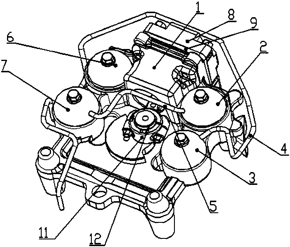
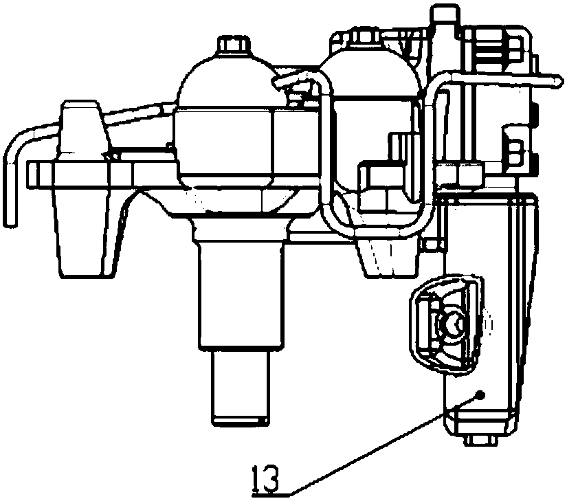
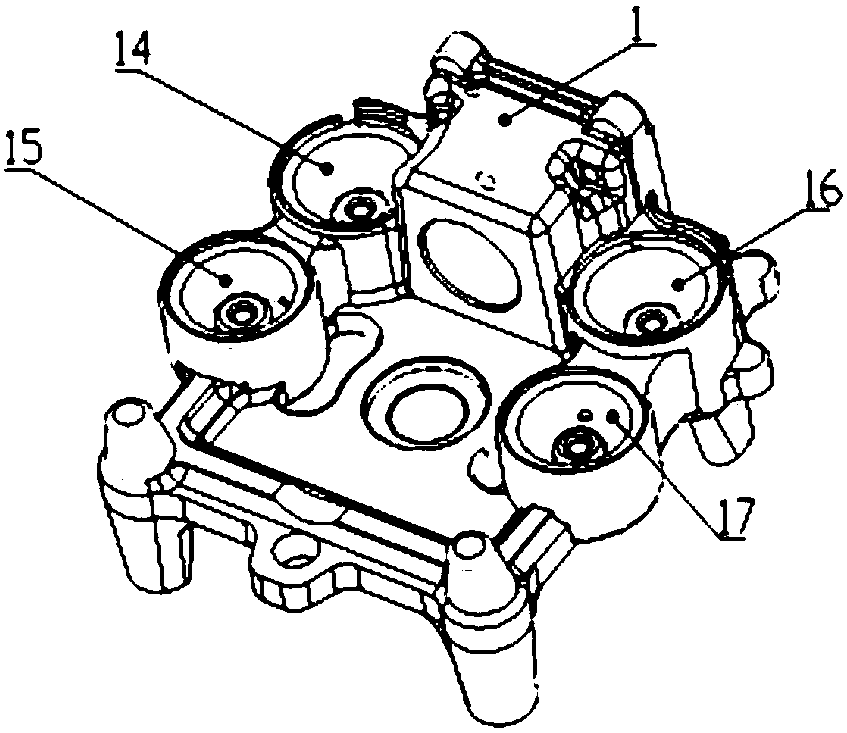
[0028] like Figure 1 to Figure 8 As shown, the noise reduction and energy-saving piston compressor includes a cylinder block 1, a cylinder head 8, a coil pipe 4, a valve plate 9, a connecting rod 11, a crankshaft 12 and a set of mufflers, wherein the valve plate 9 is arranged on the cylinder block 1 Between the valve plate and the cylinder head 8, there is an air hole connecting the cylinder block and the cylinder head, an exhaust chamber is formed between the cylinder block and the cylinder head, one end of the connecting rod 11 is connected with the piston in the cylinder block, and the other end of the connecting rod Connected to crankshaft 12.

[0029] Each muffler includes a muffler chamber and a muffler cover installed on the muffler chamber, each muffler chamber is integrated on the cy...


PUM


Abstract

The invention discloses a noise reduction and energy conservation piston type compressor. The noise reduction and energy conservation piston type compressor comprises a cylinder seat, a cylinder cover and a coiled pipe. An exhaust cavity is formed between the cylinder seat and the cylinder cover. The noise reduction and energy conservation piston type compressor further comprises a set of silencers. Each silencer comprises a silencing cavity and a silencing cover arranged on the silencing cavity; and the silencing cavities are integrated on the cylinder seat. The silencers include the first silencer, the second silencer, the third silencer and the fourth silencer. The silencing cavity of the first silencer is communicated with the exhaust cavity. The silencing cavities of the first silencer, the second silencer, the third silencer and the fourth silencer are sequentially communicated. The silencing cavity of the second silencer or the third silencer or the fourth silencer is communicated with the coiled pipe. Four-stage silencing or three-stage silencing or two-stage silencing can be achieved through the silencers. According to the piston type compressor, silencing and shock absorbing are conducted through multi-stage silencing, good silencing and vibration absorbing effects are achieved, the silencing cavities are integrated on the cylinder seat, and the structure is simple.

Description

technical field [0001] The invention relates to the technical field of compressors, in particular to a noise-reducing and energy-saving piston compressor. Background technique [0002] In order to reduce noise, existing piston compressors often install a muffler on the cylinder block or exhaust pipe to form a single-stage muffler; the biggest disadvantage of a single-stage muffler is that when kl=nπ, the transmission loss is always reduced to zero, that is There are many passing frequencies, at which the noise reduction loss of the muffler is 0, and there is no noise reduction effect at all. Although a Helmholtz exhaust resonance cavity is added to the cylinder block, because the characteristic of the Helmholtz exhaust cavity is to absorb Low-frequency noise and strong selectivity to low-frequency frequencies. Therefore, even if the Helmholtz exhaust chamber is added to the opposite side, the noise reduction frequency is extremely limited. Adding a separate muffler has a co...

Claims


Application Information

Patent Timeline
Patent Type & Authority Patents(China)
IPC IPC(8): F04B39/00F04B39/10
CPCF04B39/0083F04B39/10
Inventor 杨百昌何景云胡荣枝张文芳吴大奎王世林
Owner WUHU ABAUR MECHANICAL & ELECTRICAL
Why Eureka
Try Eureka