Automobile part cooling equipment

A technology for cooling equipment and auto parts, used in lighting and heating equipment, household refrigeration devices, household appliances, etc., can solve the problems that the accessories cannot achieve uniform cooling, cannot be cooled, and the cooling effect is not good.

Active Publication Date: 2018-06-22
CHONGQING JIANAN IND & TRADE
View PDF8 Cites 3 Cited by
  • Summary
  • Abstract
  • Description
  • Claims
  • Application Information

AI Technical Summary

Problems solved by technology

However, in the traditional air-conditioning cooling method, the accessories to be cooled are usually placed on the load-bearing object for cooling, and the contact surface between the accessories and the load-bearing object will not change, which makes it impossible to cool the contact surface between the accessories and the load-bearing object. The effect is not good, and the accessories cannot achieve uniform cooling, which reduces the cooling efficiency of the accessories, thereby reducing the molding time of the product

Method used


Image

  • Automobile part cooling equipment
  • Automobile part cooling equipment
  • Automobile part cooling equipment

Examples


Embodiment Construction

[0020] Further detailed explanation through specific implementation mode below:

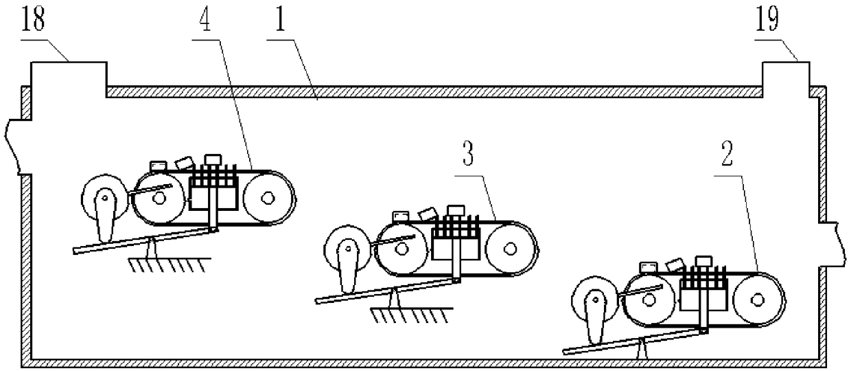
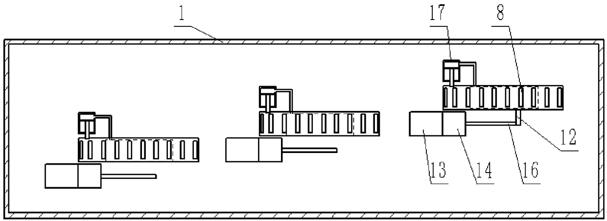
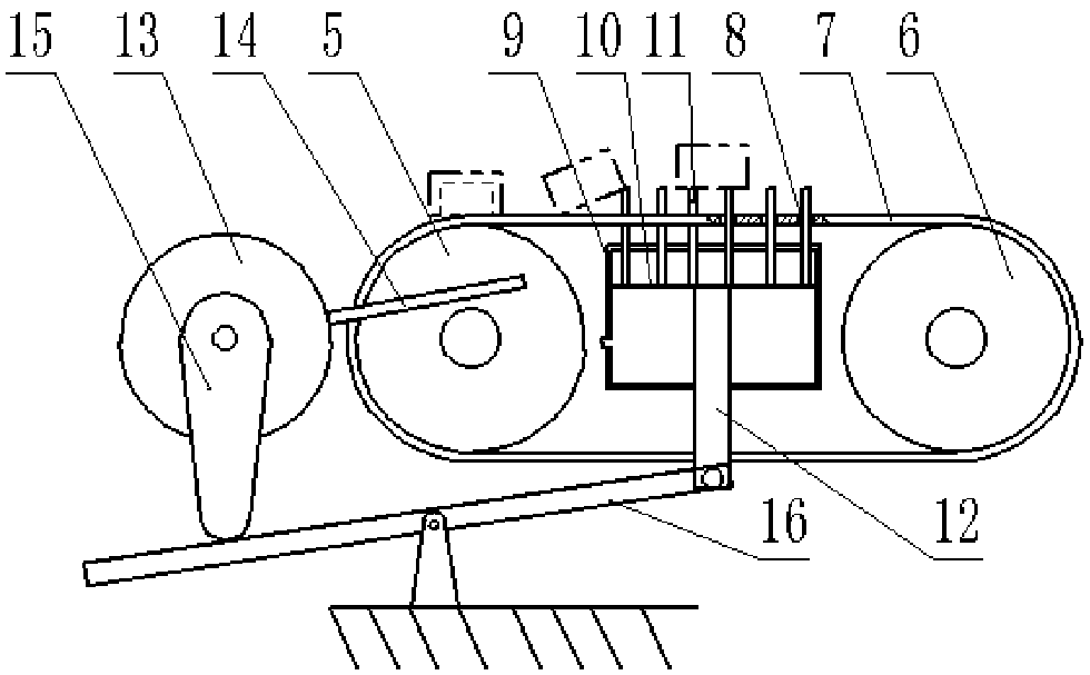
[0021] The reference signs in the accompanying drawings of the description include: cooling box 1, first-level turning unit 2, second-level turning unit 3, third-level turning unit 4, driving wheel 5, driven wheel 6, conveyor belt 7, strip-shaped through hole 8, second turning unit One cylinder block 9, slide cover 10, strip ejector rod 11, push rod 12, turning wheel 13, turning plate 14, cam 15, lever 16, second cylinder 17, air inlet 18, air outlet 19.

[0022] Such as figure 1 , figure 2 As shown, the cooling equipment for auto parts includes a cooling box 1, and the cooling box 1 is provided with an air inlet 18, an air outlet 19, a material inlet and a material outlet. The first-level turning unit 2, the second-level turning unit 3, and the third-level turning unit 4 are raised step by step. The air inlet 18 is above the three-stage overturning unit 4, the air outlet 19 is above the one-...


PUM


Abstract

The invention provides automobile part cooling equipment, and relates to the field of part cooling. The automobile part cooling equipment comprises a cooling tank, wherein an air outlet hole and an air inlet hole are formed in the upper end of the cooling tank; overturning units which are arranged in a stepped rising manner are arranged in the cooling tank; the air inlet hole is positioned above the overturning unit at the highest position; the air outlet hole is positioned above the overturning unit at the lowest position; each overturning unit comprises a conveying device, an ejection deviceand an overturning device; each conveying device comprises a conveying belt and belt pulleys which intermittently move periodically; through holes are formed in each conveying belt; each ejection device comprises a first cylinder arranged between the corresponding adjacent belt pulleys; the inside of each first cylinder is slidably connected with a sliding cover; ejector rods are arranged at theupper end of each sliding cover; a push rod is arranged at the lower end of each sliding cover; each overturning device comprises an overturning wheel and a second motor for driving the overturning wheel; each overturning wheel is provided with an overturning plate; a cam is fixed on each overturning wheel; a lever is arranged below each cam; one end of each lever is hinged to the corresponding push rod; the upper side of the other end of each lever can be abutted against the corresponding cam; and a spring is fixed on the lower side of the other end of each lever. By the scheme, the surfacesof the parts can be uniformly cooled.

Description

technical field [0001] The invention relates to a cooling device, in particular to a cooling device for auto parts. Background technique [0002] When the auto parts are just processed, the temperature is often very high, and the parts themselves will have a certain deformation due to the high temperature. If the temperature is not lowered, the accuracy of the parts will be affected in the subsequent processing, which will lead to the failure rate of the product. increase, so cooling treatment is required. Cooling treatment methods are usually divided into water cooling and air-conditioning cooling. When cooling, the accessories are usually placed on the load, and the cooling device is used to cool the surface of the accessories. However, in the traditional air-conditioning cooling method, the accessories to be cooled are usually placed on the load-bearing object for cooling, and the contact surface between the accessories and the load-bearing object will not change, which ...

Claims


Application Information

Patent Timeline
Patent Type & Authority Applications(China)
IPC IPC(8): F25D31/00
CPCF25D31/00
Inventor 肖福禄
Owner CHONGQING JIANAN IND & TRADE
Why Eureka
Try Eureka