
Vertical forced synchronous hydraulic driving device of continuous transonic speed wind tunnel nozzle section semi-flexible-wall throat piece

A driving device and forced synchronization technology, applied in the field of continuous transonic wind tunnel test, can solve the problems of inability to provide high rigidity of lateral connection, large spatial motion range, low control precision, etc., to ensure normal working efficiency, rotational inertia, etc. Small size and good spatial reusability

Active Publication Date: 2018-06-22
中国空气动力研究与发展中心设备设计及测试技术研究所 +1
View PDF8 Cites 3 Cited by
  • Summary
  • Abstract
  • Description
  • Claims
  • Application Information

AI Technical Summary

Problems solved by technology

The traditional working method of the throat block is the "frame swing type", which has the disadvantages of large overall swing mass, low control precision, large spatial movement range, and cannot provide high rigidity of lateral connection. Generally, it is only suitable for small and medium-sized wind tunnels

Method used


Image

  • Vertical forced synchronous hydraulic driving device of continuous transonic speed wind tunnel nozzle section semi-flexible-wall throat piece
  • Vertical forced synchronous hydraulic driving device of continuous transonic speed wind tunnel nozzle section semi-flexible-wall throat piece
  • Vertical forced synchronous hydraulic driving device of continuous transonic speed wind tunnel nozzle section semi-flexible-wall throat piece

Examples


Embodiment 1

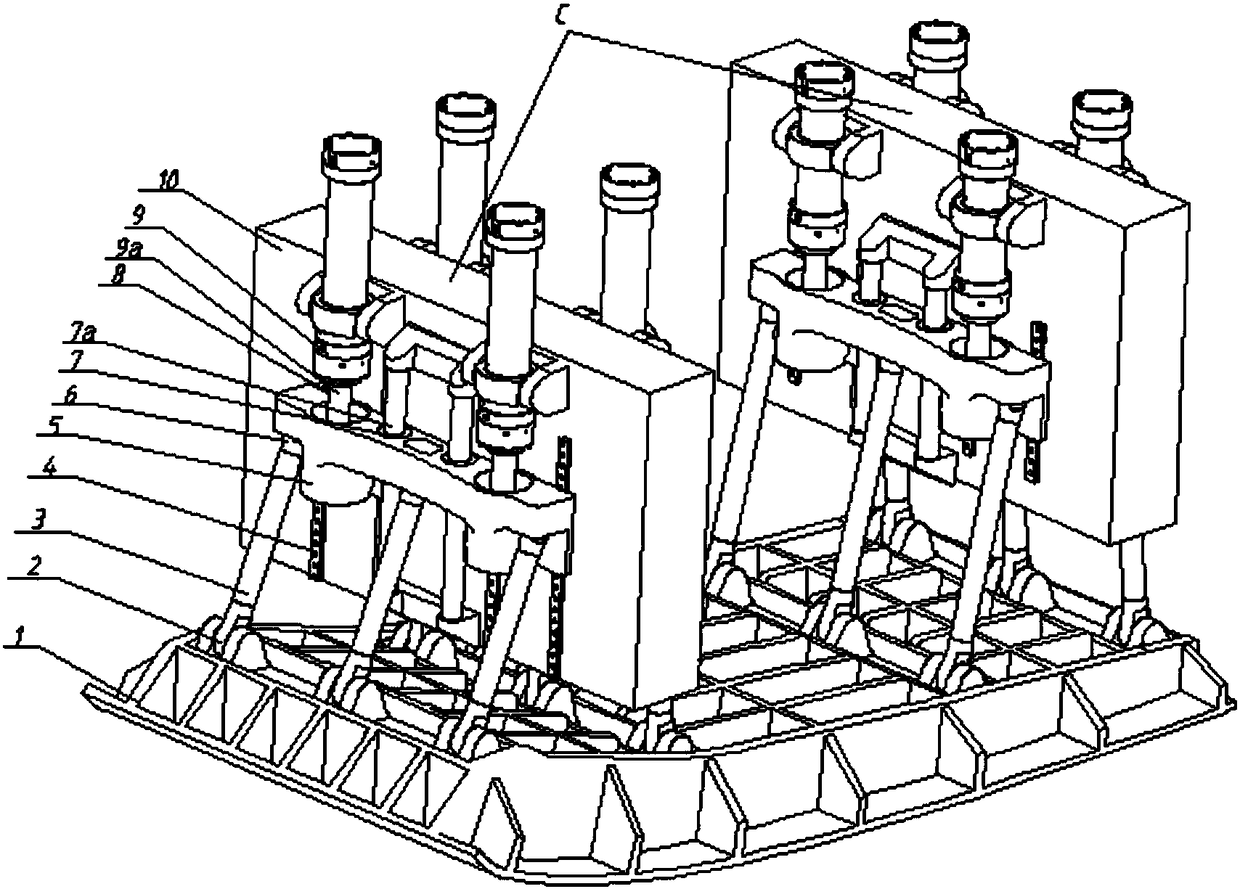
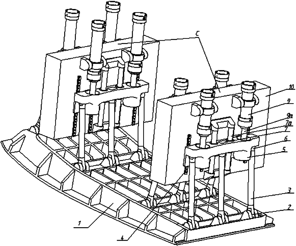
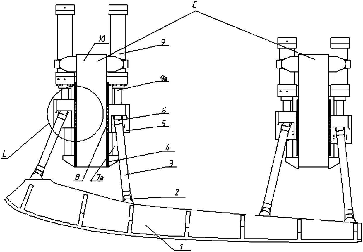
[0029] Embodiment 1: as figure 1 As shown, a vertical forced synchronous hydraulic drive device for the semi-flexible throat block of a continuous transonic wind tunnel nozzle section, comprising two units C, each unit C comprising a vertically arranged mounting seat (10), Two groups of parallel driving devices arranged symmetrically front and back are fixed on each mounting base (10); in each group of driving devices, there are two sets of guide rails (4) arranged vertically and parallel symmetrically on the left and right, and the guide rails (4) are fixed on On the mounting base (10); each set of guide rails (4) includes two vertically parallel guide rails (4); on each guide rail, a slide block (8) is arranged, and the slide block (8) can be mounted on the corresponding guide rail (4) slide up, and the slide blocks (8) on the four guide rails (4) on the left and right sets are arranged symmetrically; the slide table (5) is vertically and parallelly installed on the slide bl...

Embodiment 2

[0031] Embodiment 2: The main structure of this example is the same as that of Embodiment 1. In order to ensure the synchronous precision of driving in the group, the present invention arranges two slide blocks (8) with a certain installation distance on each group of guide rails (4). Each group of slide blocks (8) shares the same slide table (5), which compulsorily guarantees the synchronization of the two drives in each group from the mechanical level.

Embodiment 3

[0032] Embodiment 3: The main structure of this example is the same as that of Embodiment 1. In order to optimize each group of driving forces, the present invention has three groups of six hydraulic drive cylinders (9) for active displacement control, and another group of two hydraulic drive cylinders (9) ) is force passive control, and adopts vertical driving form in structure. P is a moving pair, and R is a rotating pair. The driving device is a 2P-3RR plane redundant mechanism composed of two horizontal hydraulic drive cylinders (9) and three driving connecting rods (3). Ensure the safety and reliability of the entire device.


PUM


Abstract

The invention discloses a vertical forced synchronous hydraulic driving device of a continuous transonic speed wind tunnel nozzle section semi-flexible-wall throat piece. By the vertical forced synchronous hydraulic driving device of the continuous transonic speed wind tunnel nozzle section semi-flexible-wall throat piece, planar three-degree-of-freedom movement of the continuous transonic speed wind tunnel nozzle section semi-flexible-wall throat piece is implemented, a guiding element guide track sliding block and a driving element hydraulic driving cylinder are arranged vertically, synchronism of the same group of drivers is ensured forcedly on the mechanical level by an integrated sliding table, and the mechanism principle of the whole vertical forced synchronous hydraulic driving device of the continuous transonic speed wind tunnel nozzle section semi-flexible-wall throat piece in a longitudinal plane is a planar three-degree-of-freedom ten-rod mechanism. The vertical forced synchronous hydraulic driving device of the continuous transonic speed wind tunnel nozzle section semi-flexible-wall throat piece has the characteristics of good integral rigidity, simple structure, spacemultiplexing, capability of eliminating a lateral force, high synchronization precision, large driving load, high stability, high anti-impact ability, high safety and reliability and the like.

Description

technical field [0001] The invention belongs to the technical field of continuous transonic wind tunnel tests, and relates to a vertical forced synchronous hydraulic drive device for a semi-flexible throat block of a nozzle section of a continuous transonic wind tunnel, which is used to realize a continuous transonic wind tunnel Planar three-degree-of-freedom motion of a semi-flexible throat block in a nozzle section. Background technique [0002] The wind tunnel is an important test device used to verify whether the aerodynamic shape of various types of aerospace vehicles and high-speed EMUs is reasonable. Its main principle is to simulate the external gas flow field characteristics (Mach number, Reynolds number, etc.) number, Prandtl number, etc.), and make a series of evaluations on the measured parameters of the tested object in the simulated flow field, so as to realize the prediction of its characteristics under real working conditions. According to the way the flow f...

Claims


Application Information

Patent Timeline
Patent Type & Authority Applications(China)
IPC IPC(8): G01M9/04
CPCG01M9/04
Inventor 宋代平李坤陈振华尹永涛廖文林张浩张志秋谢志江皮阳军刘飞
Owner 中国空气动力研究与发展中心设备设计及测试技术研究所
Learn More