
A photoresist soft drying device

A photoresist and soft-baking technology, applied in optics, optomechanical equipment, instruments, etc., can solve the problems of insufficient exhaust capacity, residual photoresist, soft-bake exhaust alarm and downtime, etc., to avoid exhaust downtime , Increase the exhaust pressure, improve the effect of product yield

Active Publication Date: 2021-06-01
WUHAN CHINA STAR OPTOELECTRONICS TECH CO LTD
View PDF0 Cites 0 Cited by
  • Summary
  • Abstract
  • Description
  • Claims
  • Application Information

AI Technical Summary

Problems solved by technology

[0004] At present, the design of the soft drying device of CSOT T3 Photo machine has insufficient exhaust capacity, resulting in the photoresist particles produced during the process cannot be completely extracted out of the process chamber, and the photoresist particles fall on the substrate, resulting in photoresist residue
At the same time, the design defect of the soft-bake exhaust valve caused the extracted photoresist particles to condense on the exhaust valve, causing friction between the valve and the horizontal rubber pad, causing the soft-bake exhaust alarm to go down

Method used


Image

  • A photoresist soft drying device
  • A photoresist soft drying device
  • A photoresist soft drying device

Examples


Embodiment Construction

[0029] The following descriptions of the various embodiments refer to the accompanying drawings to illustrate specific embodiments in which the invention may be practiced. The directional terms mentioned in the present invention, such as [top], [bottom], [front], [back], [left], [right], [inside], [outside], [side], etc., are only for reference The orientation of the attached schema. Therefore, the directional terms used are used to illustrate and understand the present invention, but not to limit the present invention. In the figures, structurally similar elements are denoted by the same reference numerals.

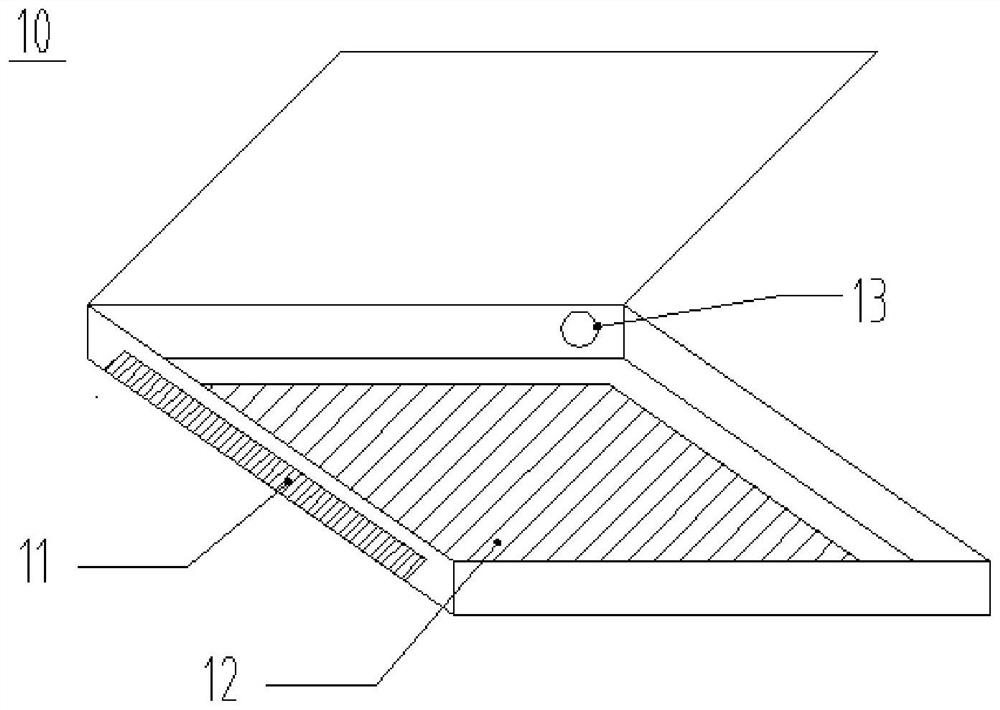
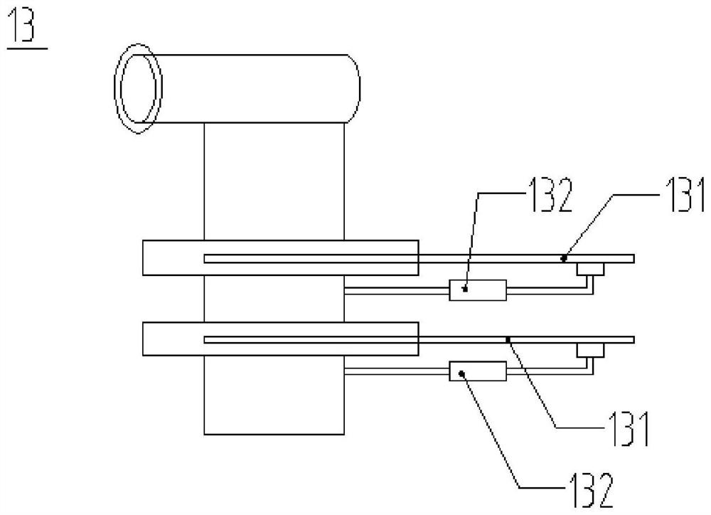
[0030] Such as figure 1 As shown, it is a schematic structural diagram of a photoresist soft-baking device in the prior art. The device includes a chamber 10, a hot air knife 11 is provided at the left end of the chamber 10, and a row of The gas port 13 and the substrate 12 coated with photoresist are placed in the chamber 10 . Such as figure 2 As shown, it is a sc...


PUM


Abstract

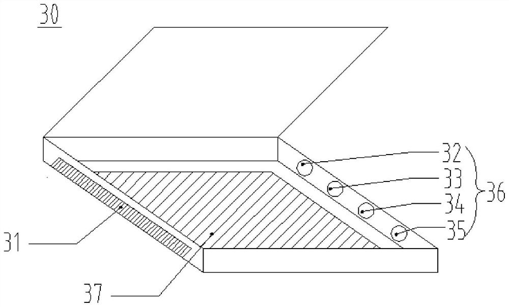
The invention provides a photoresist soft-baking device, comprising: a chamber for accommodating a substrate coated with photoresist on the surface; a hot plate arranged in the chamber for heating the substrate; a hot air knife , arranged at one end of the chamber, for causing the chamber to generate an air flow in a predetermined direction; and an exhaust port, corresponding to the hot air knife, arranged at the other end of the chamber for discharging the photolithography Photoresist particles formed by evaporating the glue after high-temperature baking; wherein, a pressure-swing vacuum adsorption device is installed in the exhaust pipe corresponding to the exhaust port to adjust the exhaust pressure to absorb the photoresist particles; One end of the exhaust port is provided with an exhaust valve to control the exhaust of the soft drying device.

Description

technical field [0001] The invention relates to the technical field of display panel manufacturing, in particular to a photoresist soft-baking device. Background technique [0002] In the manufacturing process of the display panel, the production process of the TFT side exposure part includes: the glass substrate is cleaned, coated with photoresist (Coater), baked (Pre-bake), and then enters the exposure machine (Exposure), using MASK Define the pattern on the photoresist on the glass substrate; and then display the pattern through the development process (Developer). [0003] After the coating process of the glass substrate is completed, the substrate enters a soft baking (Soft Bake) unit for a soft baking process. At present, the CSOT T3 Photo machine used in the soft baking process of the substrate is in the continuous delivery process of the Photo Line. For the yellow light process, the photoresist residue has a very important impact on the product yield, and the small ...

Claims


Application Information

Patent Timeline
Patent Type & Authority Patents(China)
IPC IPC(8): G03F7/16
CPCG03F7/168
Inventor 李威
Owner WUHAN CHINA STAR OPTOELECTRONICS TECH CO LTD
Learn More