Robot, and pose estimation method and device based on marker

A pose estimation and robot technology, applied in the field of computer vision, can solve the problems of pitch angle and roll angle redundancy, large pose error, etc., and achieve the effect of precise pose

Inactive Publication Date: 2018-06-22
SMART DYNAMICS CO LTD
View PDF5 Cites 23 Cited by
  • Summary
  • Abstract
  • Description
  • Claims
  • Application Information

AI Technical Summary

Problems solved by technology

[0006] The object of the present invention is to provide a robot and its marker-based pose estimation method, device, and computer-readable storage medium, aiming to solve the problem of pitch angle calculated by the p3p algorithm for a robot that only needs two-dimensional plane navigation. and roll angle are redundant information, which causes the problem that the calculated pose error is too large

Method used


Image

  • Robot, and pose estimation method and device based on marker
  • Robot, and pose estimation method and device based on marker
  • Robot, and pose estimation method and device based on marker

Examples


Embodiment 1

[0024] see figure 1 The marker-based pose estimation method for a robot provided in Embodiment 1 of the present invention includes the following steps: It should be noted that if there are substantially the same results, the marker-based pose estimation method for a robot in the present invention does not use figure 1 The flow sequence shown is limited.

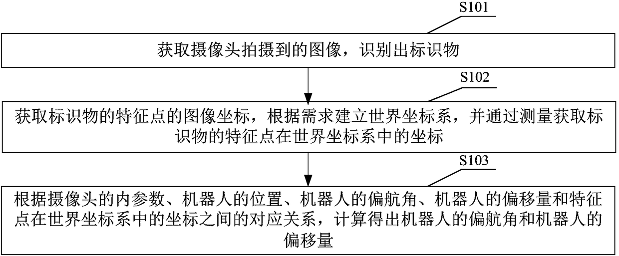
[0025] S101. Acquire an image captured by a camera, and identify a marker.

[0026] The plane where the marker is located is a plane parallel to the camera. For example, markers are attached to the ceiling or floor of the space where the robot is located.

[0027] The shape of the marker can be arbitrary, such as circle, quadrangle, pentagon, irregular shape, etc.

[0028] In Embodiment 1 of the present invention, S101 may specifically include the following steps:

[0029] Obtain the image captured by the camera;

[0030] convert the image to grayscale;

[0031] Using adaptive binarization operations and contour search ...

Embodiment 2

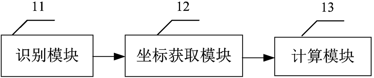
[0049] see figure 2 The marker-based pose estimation device for a robot provided in Embodiment 2 of the present invention includes:

[0050] The identification module 11 is used to acquire the image captured by the camera and identify the marker;

[0051] The coordinate acquisition module 12 is used to obtain the image coordinates of the feature points of the marker, establish a world coordinate system according to requirements, and obtain the coordinates of the feature points of the marker in the world coordinate system by measuring;

[0052] The calculation module 13 is used to calculate the yaw of the robot according to the correspondence between the internal parameters of the camera, the position of the robot, the yaw angle of the robot, the offset of the robot, and the coordinates of the feature points in the world coordinate system Corners and robot offsets.

[0053] The robot pose estimation device based on markers provided in Embodiment 2 of the present invention an...

Embodiment 3

[0055] Embodiment 3 of the present invention provides a computer-readable storage medium. The computer-readable storage medium stores a computer program. The steps of the pose estimation method.


PUM


Abstract

The invention is suitable for the machine vision field and especially relates to a robot, and a pose estimation method and a device based on a marker. The method comprises the following steps of acquiring an image shot by a camera and identifying the marker; acquiring the image coordinate of the characteristic point of the marker, according to a demand, establishing a world coordinate system, andthrough measurement, acquiring the coordinate of the characteristic point of the marker in the world coordinate system; and according to a corresponding relation among the inner parameter of the camera, the position of the robot, the yaw angle of the robot, the offset of the robot and the coordinate of the characteristic point in the world coordinate system, calculating the yaw angle of the robotand the offset of the robot. In the invention, a p3p algorithm is not adopted so that the redundant pitch angle and the roll angle of the robot which only needs two-dimensional plane navigation do notneed to be calculated, and a calculated pose is accurate.

Description

technical field [0001] The invention belongs to the field of computer vision, and in particular relates to a robot and a marker-based pose estimation method and device thereof. Background technique [0002] Pose estimation is an important field in computer vision, and it has many applications, such as augmented reality, virtual reality, and object spatial positioning (such as spatial pose estimation of UAVs). [0003] Commonly used pose estimation algorithms are generally divided into vision-based and sensor-based pose estimation algorithms. The vision-based pose estimation algorithm has gradually replaced the image-based pose estimation algorithm due to its low cost, anti-electromagnetic interference, and high accuracy. Sensor pose estimation. The vision-based pose estimation algorithm is divided into single-purpose and multi-purpose based algorithms. Compared with multi-purpose pose estimation algorithms, the single-purpose pose estimation algorithm has the advantages of ...

Claims


Application Information

Patent Timeline
Patent Type & Authority Applications(China)
IPC IPC(8): G06T7/73
CPCG06T7/73G06T2207/30244
Inventor 辛冠希徐栋王可可沈剑波
Owner SMART DYNAMICS CO LTD
Why Eureka
Try Eureka