Magnetic stripe positioning method and device

A positioning method and magnetic stripe technology, which is applied in the field of data processing network, can solve the problems of inaccurate magnetic stripe positioning and achieve the effect of eliminating interference and accurate positioning

Active Publication Date: 2018-06-22
SHENZHEN YIHUA COMP +2
View PDF5 Cites 4 Cited by
  • Summary
  • Abstract
  • Description
  • Claims
  • Application Information

AI Technical Summary

Problems solved by technology

However, since there are not only magnetic spots on the magnetic strips in banknotes, but also many magnetic noises, this method is not accurate for the positioning of the magnetic strips

Method used


Image

  • Magnetic stripe positioning method and device
  • Magnetic stripe positioning method and device
  • Magnetic stripe positioning method and device

Examples


no. 1 example

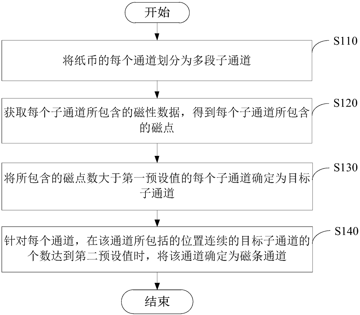
[0026] Please refer to figure 2 , figure 2 It is a flow chart of a magnetic stripe positioning method provided in the first embodiment of the present invention, and the method is applied to electronic equipment. The following will be image 3 The process shown is described in detail, and the method includes:

[0027] Step S110: Divide each channel of banknotes into multiple sub-channels.

[0028] The electronic device can scan the banknotes, so that the obtained banknote data is divided into M rows and N columns, for example (1260 rows and 18 columns), wherein the electronic device can determine each column as a channel, for example, 18 channels. Thus, each channel contains 1260 lines. Then, the electronic device divides each channel of the banknote into multiple sub-channels according to the rule that each L line is a segment, wherein, L

[0029] Further, the electro...

no. 2 example

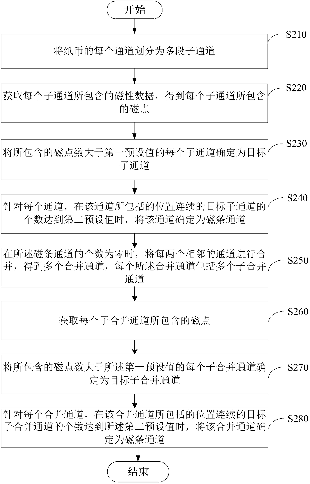
[0043] Please refer to image 3 , image 3 It is a flowchart of a magnetic stripe positioning method provided by the second embodiment of the present invention, and the method is applied to electronic equipment. The following will be image 3 The process shown is described in detail, and the method includes:

[0044] Step S210: Divide each channel of banknotes into multiple sub-channels.

[0045] Step S220: Obtain the magnetic data contained in each sub-channel, and obtain the magnetic points contained in each sub-channel.

[0046] Step S230: Determine each sub-channel whose number of magnetic points is greater than a first preset value as a target sub-channel.

[0047] Step S240: For each channel, when the number of consecutive target sub-channels included in the channel reaches a second preset value, determine the channel as a magnetic stripe channel.

[0048] For the specific implementation process of the above steps S210-S240, please refer to the first embodiment.

...

no. 3 example

[0057] Please refer to Figure 4 , Figure 4 It is a structural block diagram of a magnetic strip positioning device 400 provided by the third embodiment of the present invention. The following will be Figure 4 The structure block diagram shown is described, and the shown device includes:

[0058] A division module 410, configured to divide each channel of banknotes into multiple sub-channels;

[0059] An acquisition module 420, configured to acquire the magnetic data contained in each sub-channel, and obtain the magnetic points contained in each sub-channel;

[0060] A determining module 430, configured to determine each sub-channel whose number of magnetic points is greater than a first preset value as a target sub-channel;

[0061] The determining module 430 is further configured to, for each channel, determine the channel as a magnetic stripe channel when the number of consecutive target sub-channels included in the channel reaches a second preset value.

[0062] In ...


PUM


Abstract

The invention provides a magnetic stripe positioning method and device. According to the invention, each channel of a paper note is divided into a plurality of sub channels. Magnetic data contained byeach sub channel is acquired and magnetic dots contained by each sub channel are then acquired. Sub channels whose magnetic dot number is greater than a first preset value are determined as target sub channels. Channels whose target sub channel number is greater than a second preset value are determined as magnetic strip channels, wherein the target sub channels are continuous in position. A method of determining channels having the largest magnetic dot number as the magnetic strip channel directly is rejected, so that magnetic noise and interference caused by serial number areas of paper notes are eliminated. Therefore, accurate positioning of paper note magnetic strips is realized.

Description

technical field [0001] The invention relates to the field of data processing networks, in particular to a magnetic stripe positioning method and device. Background technique [0002] The security line (magnetic stripe) of the RMB is an important feature of counterfeiting, and its accurate positioning is the premise of counterfeiting. [0003] A common magnetic stripe positioning method is to count the number of magnetic dots in each channel of the banknote, and determine the channel with the largest number of magnetic dots as the magnetic stripe. However, since there are not only magnetic dots on the magnetic strips in banknotes, but also many magnetic noises, this method is not accurate for the positioning of the magnetic strips. Contents of the invention [0004] In view of this, the purpose of the embodiments of the present invention is to provide a magnetic stripe positioning method and device to alleviate the problem of inaccurate positioning of the magnetic stripe b...

Claims


Application Information

Patent Timeline
Patent Type & Authority Applications(China)
IPC IPC(8): G07D7/04G07D11/00
CPCG07D7/04G07D11/16
Inventor 赵玉民李杰
Owner SHENZHEN YIHUA COMP
Why Eureka
Try Eureka