Controllable solid phase micro-extraction handle
A controllable, extraction technology, applied in measuring devices, instruments, scientific instruments, etc., can solve the problems of limited types of solid-phase microextraction handles and high prices, and achieve improved performance and utilization, low cost, and easy replacement. Effect
- Summary
- Abstract
- Description
- Claims
- Application Information
AI Technical Summary
Problems solved by technology
Method used
Image

Examples
Embodiment Construction
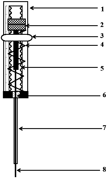
[0029] Such as figure 1 As shown, the controllable solid-phase microextraction handle includes a handle barrel 1, a metal sleeve 7 and an extraction probe 8 with stainless steel wire or silicon oxide as the support material. The handle barrel 1 is provided with a positioning ring 3, and is embedded with a push button 2 arranged on the zigzag guide rail 5; the lower end of the handle barrel 1 is provided with a metal sleeve fixing bracket 6, and the metal sleeve fixing bracket 6 and the metal sleeve 7 connected; the bottom end of the push button 2 is connected with the metal sleeve fixing support 6;
[0030] Wherein: the bottom end of the push button 2 is connected with the metal sleeve fixing bracket 6 through the spring 4 .
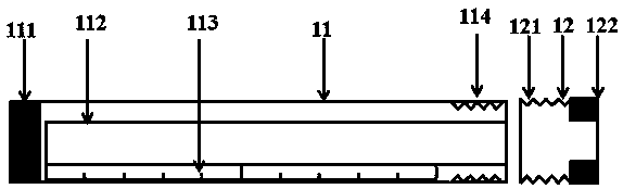
[0031] The handle barrel 1 comprises an upper half 11 and a lower half 12 connected together (see figure 2 ), the upper half 11 is provided with a scale line 113, one end of which is provided with a guide rail fixing groove 111, and a push button slid...
PUM
 Abstract
Description
Claims
Application Information
PatSnap Eureka turns technology decisions into work you can execute. Powered by our Innovation Knowledge Graph, it runs expert workflows across engineering, life sciences, materials and intellectual property. Get your review-ready output in minutes.


