Impact Wrenches, Wrench Systems, and Methods of Use

Active Publication Date: 2019-12-19
MACDONALD JEFFREY DEAN
View PDF0 Cites 0 Cited by
  • Summary
  • Abstract
  • Description
  • Claims
  • Application Information

AI Technical Summary

Benefits of technology

[0009]As may be disclosed, taught, and/or suggested herein to the skilled artisan, the presen

Problems solved by technology

However, in most applications, only one tool will be used at a time to engage a fitting and the other

Method used


Image

  • Impact Wrenches, Wrench Systems, and Methods of Use
  • Impact Wrenches, Wrench Systems, and Methods of Use
  • Impact Wrenches, Wrench Systems, and Methods of Use

Examples


Embodiment Construction

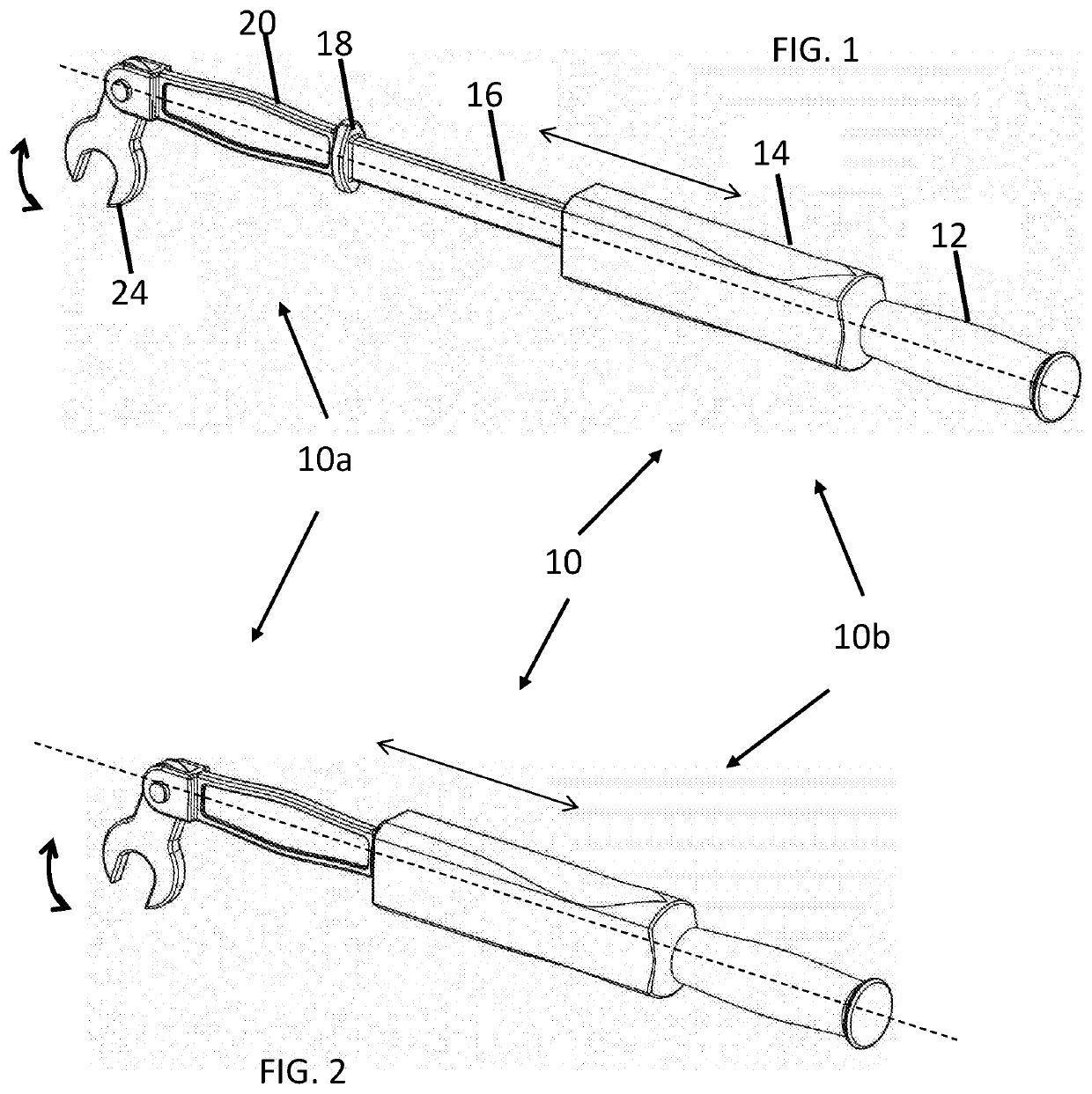
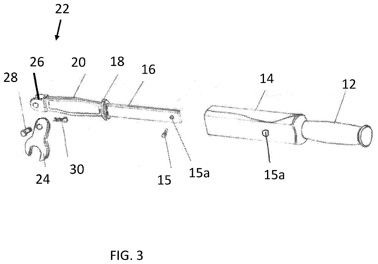
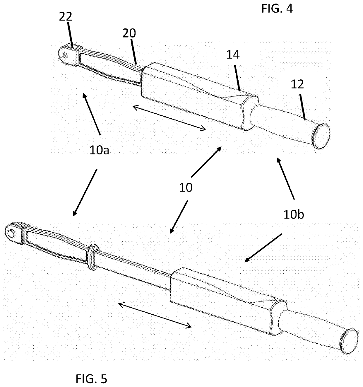
[0014]Impact wrenches, wrench systems, and methods of the present invention are described herein, by way of example and otherwise. FIGS. 1 and 2 illustrate various exemplary impact wrenches or wrench systems 10 including a head or head end / portion 10a, and a handle or handle end / portion 10b. The head 10a and handle 10b may also be referred to as the fixed and moving portions, respectively, as the handle 10b will generally be moved relative to the head 10a in operation of the wrench 10.

[0015]FIGS. 1 and 2 show various embodiments with the handle 10b in different positions relative to the head end 10a. FIG. 1 shows the handle 10b in an extended position relative to the head 10a. FIG. 2 shows the handle 10b in an impact position relative to the head 10a.

[0016]The wrench 10 may be sized and shaped by the skilled artisan to achieve a desired level of impact. It will be further appreciated that the wrench system 10 may include various head ends 10a that may be interchanged with various h...


PUM


Abstract

Impact wrenches of the present invention generally include a handle including a slide hammer that is movable relative to a head end of the wrenches. The head includes a force translation portion positioned to translate force applied to the force translation portion from the slide hammer to rotate a tool connected to the force translation portion. When the tool is engaged with a rotatable fitting a substantially linear force applied with the slide hammer may be translated to the tool, which converts at least a portion of the force to a rotational force to loosen or tighten the fitting.

Description

CROSS-REFERENCE TO RELATED APPLICATIONS[0001]This non-provisional patent application claims the benefit of and priority to U.S. Provisional Patent Application No. 62 / 686,087 filed Jun. 17, 2006, which is incorporated herein by reference in its entirety.BACKGROUND OF THE INVENTIONField of the Invention[0002]The present disclosure relates to wrenches. More particularly the present disclosure relates to impact wrenches that enable the increased application of force to fittings, particularly in areas with reduced access to the fitting.Background Art[0003]Many different types and sizes of wrenches and other tools have been developed over the years to facilitate the tightening and loosening of rotatable fittings (i.e., nuts, bolts, screws, etc.). In some instances, the fittings may end up overly tight, so the fitting is not easily loosened using traditional tools and not accessible or easily loosened by power tools. In other instances, it may be desirable to tighten a fitting beyond a poi...

Claims


Application Information

Patent Timeline
IPC IPC(8): B25B19/00B25B23/00B25B23/16B25D1/16
CPCB25B19/00B25D1/16B25B23/16B25B23/0035B25B23/0028
Inventor MACDONALD, JEFFREY DEAN
Owner MACDONALD JEFFREY DEAN
Why Eureka
Try Eureka