Dynamic slab cutting design method and system
A design method and design system technology, applied in the field of steelmaking information, can solve the problems of increasing inventory, transportation and cutting costs, outputting unplanned blanks, and low plan execution rate, so as to improve the level of production organization and reduce blanks The effect of cutting loss
Inactive Publication Date: 2018-06-26
JIANGSU JINHENG INFORMATION TECH CO LTD
View PDF4 Cites 6 Cited by
- Summary
- Abstract
- Description
- Claims
- Application Information
AI Technical Summary
Problems solved by technology
Due to the instability of the tapping amount of the converter, when the actual amount of molten steel in a furnace is less than the planned amount of molten steel, the planned slab will not be produced. In order to meet the needs of the order, the production must be scheduled again, which will bring great impact to the planning and production organization. There are many problems; when the actual amount of molten steel in a furnace is greater than the planned amount of molten steel, it will lead to the output of unplanned blanks, which will increase related costs such as inventory, transportation and cutting
[0003] In an environment where market demand is increasingly personalized, user orders present the characteristics of multiple varieties and small batc
Method used
View moreImage
Smart ImageViewing Examples
Examples
 PUM
 Abstract
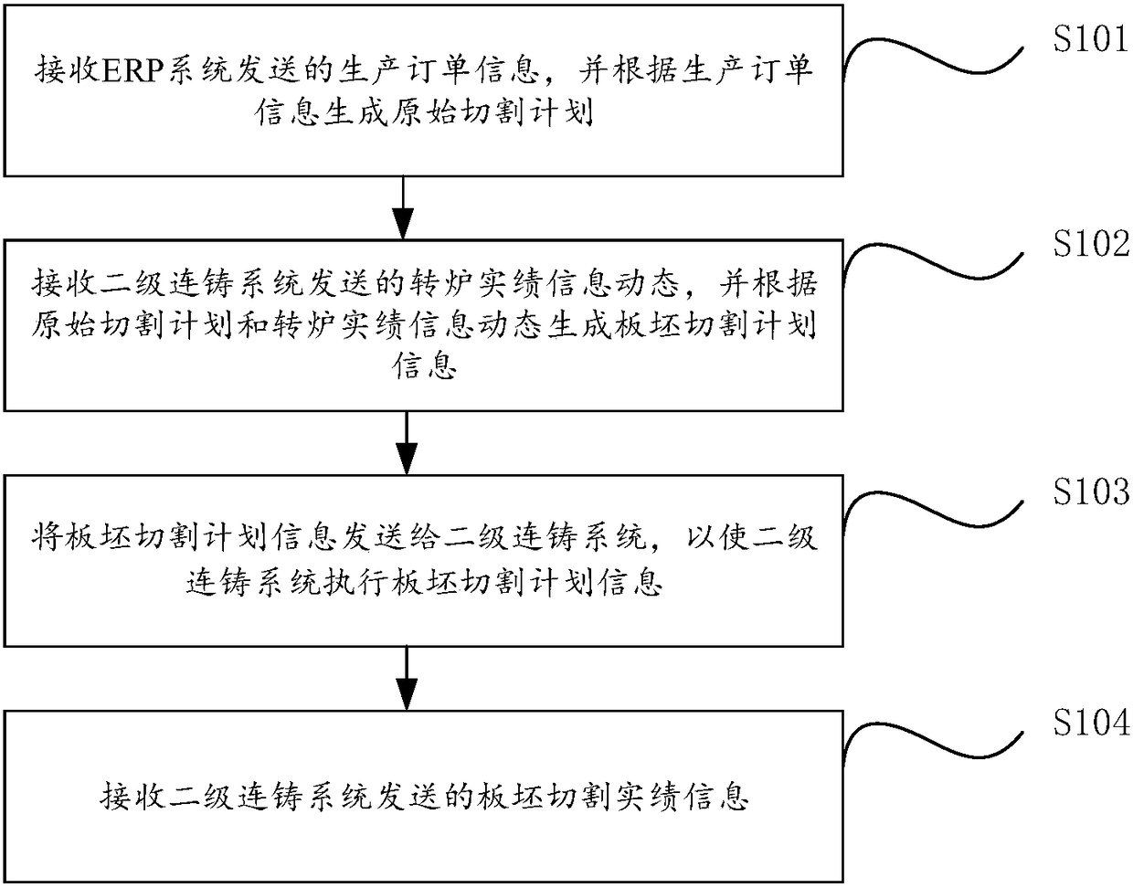
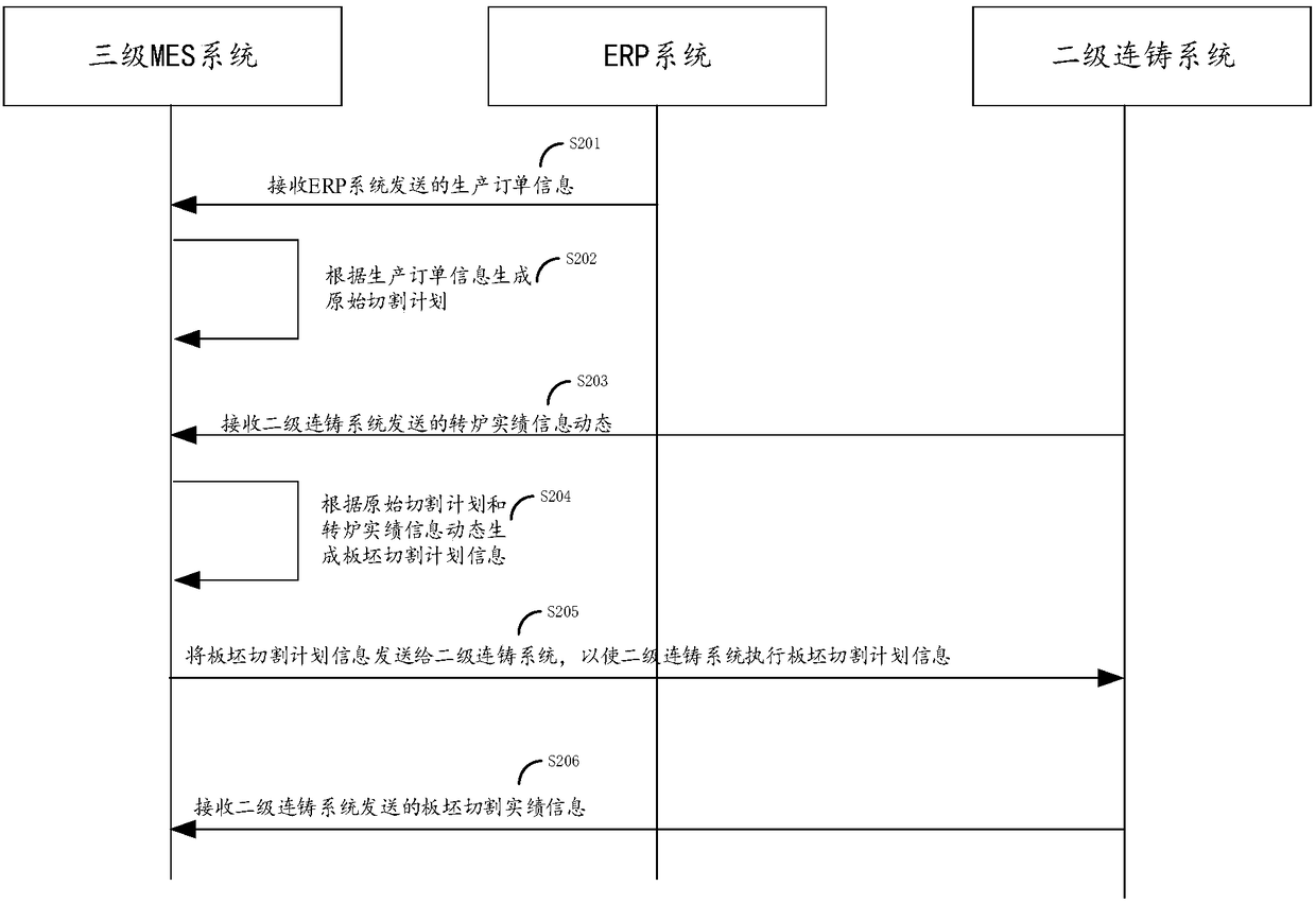
The invention provides a dynamic slab cutting design method and system. The method comprises the following steps that: production order information sent by an ERP system is received, and an original cutting plan is generated according to the production order information; a converter actual performance information dynamic condition sent by a secondary continuous casting system is received, and slabcutting plan information is generated according to the original cutting plan and the converter actual performance information dynamic condition; and the slab cutting plan information is sent to the secondary continuous casting system, so that the secondary continuous casting system executes the slab cutting plan information; and slab cutting actual performance information sent by the secondary continuous casting system is received. With the dynamic slab cutting design method and system of the invention adopted, binding relationships between original heat slab cutting plans and heat numbers are broken; great inconvenience brought to plan execution caused by the instability of heat steel tapping can be eliminated; an execution plan with plan numbers adopted as units is formed; production organization level can be improved; and residual slab cutting loss can be decreased.
Description
technical field [0001] The invention relates to the technical field of steelmaking information, in particular to a dynamic slab cutting design method and system. Background technique [0002] At present, the secondary system of continuous casting in steelmaking plants generally executes the slab cutting plan in units of heats. Due to the instability of the tapping amount of the converter, when the actual amount of molten steel in a furnace is less than the planned amount of molten steel, the planned slab will not be produced. In order to meet the needs of the order, the production must be scheduled again, which will bring great impact to the planning and production organization. There are many problems; when the actual amount of molten steel in a furnace is greater than the planned amount of molten steel, it will lead to the output of unplanned blanks, which will increase related costs such as inventory, transportation and cutting. [0003] In an environment where market de...
Claims
Login to View More Application Information
Patent Timeline
 IPC IPC(8): G06Q10/10G06Q50/04
CPCG06Q10/103G06Q50/04Y02P90/30
Inventor 孙茂杰杨猛郭丽耿学玉李福存章劲柏
Owner JIANGSU JINHENG INFORMATION TECH CO LTD
Features
- R&D
- Intellectual Property
- Life Sciences
- Materials
- Tech Scout
- Unparalleled Data Quality
- Higher Quality Content
- 60% Fewer Hallucinations
Learn More Browse by: Latest US Patents, China's latest patents, Technical Efficacy Thesaurus, Application Domain, Technology Topic, Popular Technical Reports.
© 2025 PatSnap. All rights reserved.Legal|Privacy policy|Modern Slavery Act Transparency Statement|Sitemap|About US| Contact US: help@patsnap.com


