Industrial dust collector device

A technology for industrial dust collectors and dust collectors, which is applied to coupling devices, parts of connecting devices, and devices for joining/disconnecting connecting parts, etc., can solve the problems of inconvenient dust removal operation, high power of industrial dust collectors, interruption of power supply, etc. To achieve the effect of increasing the safety of electricity consumption

Inactive Publication Date: 2018-06-26
广州创码信息科技有限公司
View PDF4 Cites 9 Cited by
  • Summary
  • Abstract
  • Description
  • Claims
  • Application Information

AI Technical Summary

Problems solved by technology

[0002] Industrial dust collectors are widely used in industrial production. However, industrial dust collectors have relatively high power. Some factories are specially equipped with power distribution boxes for plugging and power supply of dust collectors. There are sockets in the power distribution box. However, these plugs The seat setting mode is single, and its internal conductive sheet is set relatively outside. This conductive sheet is easily touched by the metal sheet or metal rod. Therefore, when people who lack safety awareness insert the metal shee

Method used


Image

  • Industrial dust collector device
  • Industrial dust collector device
  • Industrial dust collector device

Examples


Embodiment Construction

[0023] All features disclosed in this specification, or steps in all methods or processes disclosed, may be combined in any manner, except for mutually exclusive features and / or steps.

[0024] Any feature disclosed in this specification (including any appended claims, abstract and drawings), unless expressly stated otherwise, may be replaced by alternative features which are equivalent or serve a similar purpose. That is, unless expressly stated otherwise, each feature is one example only of a series of equivalent or similar features.

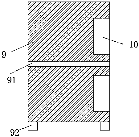
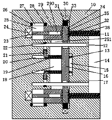
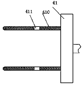
[0025] Such as Figure 1 to Figure 4As shown, a kind of industrial dust remover device of the device of the present invention includes a cabinet 9 and an electrical connector 41 connected with the dust remover. There are at least two sets of electric sockets 10, the right end of the electric socket 10 is provided with a side groove 14 with the opening facing right and matched with the electric connector 41, and the upper and lower sides of th...


PUM


Abstract

The invention discloses an industrial dust collector device, which comprises a machine case and an electric connector connected with a dust collector, wherein support legs are arranged at the bottom of the machine case; at least two or more groups of electric connection seats are separately arranged in the machine case through a partition plate from top to bottom; an edge slot of which a port is toward the right and which is matched with the electric connector is arranged in the right end surface of each electric connection seat; inserting grooves of which the ports are toward the right are arranged in a left end wall of each edge slot from top to bottom in a peer-to-peer manner; a connection cavity communicating with two inserting grooves is arranged between the two inserting grooves; first sliding grooves communicating with the corresponding connection cavity are arranged in the left end wall of each connection cavity from top to bottom in a peer-to-peer manner; a communicating second sliding groove is arranged between each first sliding groove and the corresponding inserting groove; a first sliding arm is arranged in each second sliding groove in a sliding manner; a ball is arranged on the end surface, toward the corresponding first sliding groove, of each first sliding arm; a power supply sheet is fixedly arranged on the end surface, toward the corresponding inserting groove, of each first sliding arm; and a sliding cavity which extends from left to right is arranged in an end wall, back to the corresponding connection cavity, of each inserting groove.

Description

technical field [0001] The invention relates to the field of dust collectors, in particular to an industrial dust collector device. Background technique [0002] Industrial dust collectors are widely used in industrial production. However, industrial dust collectors have relatively high power. Some factories are specially equipped with power distribution boxes for plugging and power supply of dust collectors. There are sockets in the power distribution box. However, these plugs The seat setting mode is single, and its internal conductive sheet is set relatively outside. This conductive sheet is easily touched by the metal sheet or metal rod. Therefore, when people who lack safety awareness insert the metal sheet or rod into the socket It is easy to cause electric shock accidents and casualties; at the same time, the dust collector needs to move frequently during the dust removal operation, and the dust collector only relies on the friction between the plug connector and the ...

Claims


Application Information

Patent Timeline
IPC IPC(8): H01R13/639H01R13/516H01R13/62
CPCH01R13/516H01R13/62H01R13/639
Inventor 袁承宇
Owner 广州创码信息科技有限公司
Why Eureka
Try Eureka