Magnetic control type energy-saving welding gun structure

A magnetic control, welding torch technology, applied in valve details, welding equipment, gas flame welding equipment, etc., can solve the problems of polluting the environment, wasting gas, gas leakage, etc., achieving convenient on-off control, preventing tempering, and fast response Effect

Pending Publication Date: 2018-06-29
上海晶珊电子科技有限公司
View PDF0 Cites 2 Cited by
  • Summary
  • Abstract
  • Description
  • Claims
  • Application Information

AI Technical Summary

Problems solved by technology

[0003] In order to solve the problems in the prior art that the adjusting valve of the welding torch easily leads to gas leakage, wasting gas and polluting the environment, the present invention provides a magnetically controlled e

Method used


Image

  • Magnetic control type energy-saving welding gun structure
  • Magnetic control type energy-saving welding gun structure
  • Magnetic control type energy-saving welding gun structure

Examples


Embodiment 1

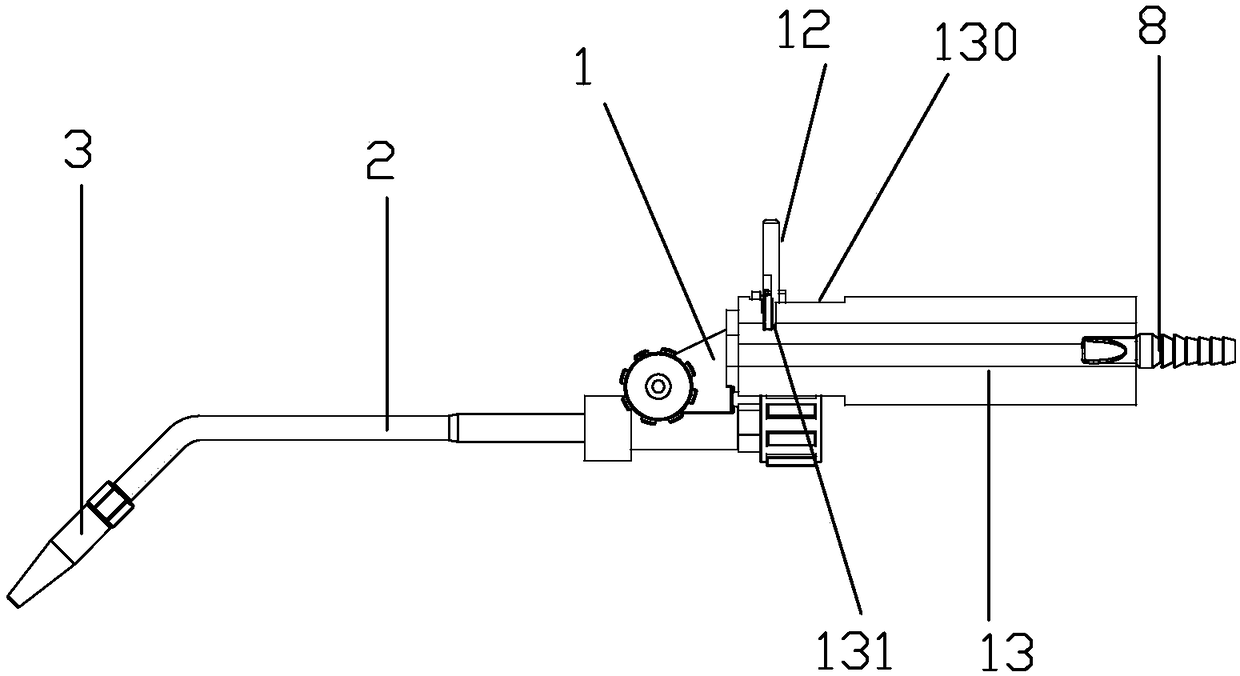
[0027] Embodiment 1: as figure 1 , figure 2 and image 3 The structure of a magnetically controlled energy-saving welding torch shown includes a connecting seat 1 and an air jet pipe 2. One end of the air jet pipe is connected to the connecting seat, the other end of the air jet pipe is provided with a welding tip 3, and the connecting seat is provided with two parallel Connecting pipe 4, the two connecting pipes communicate with the jet pipe through the flow channel in the connecting seat; the inlet end of the connecting pipe 4 is provided with a valve seat 5, and the valve seat is provided with two independent valve chambers 50, the front end of the valve seat There are two outlet air passages 51 correspondingly connected with the valve chamber, the inner end of the outlet air passage extends into the valve chamber to form a tapered convex ring 52, and the two connecting pipes are connected with the outer ends of the outlet air passage in one-to-one correspondence , the v...

Embodiment 2

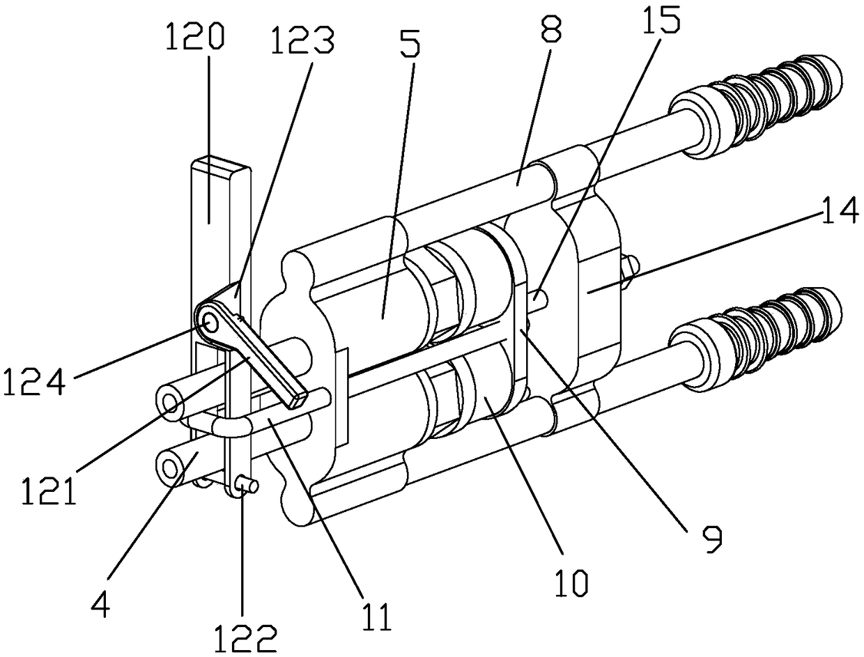
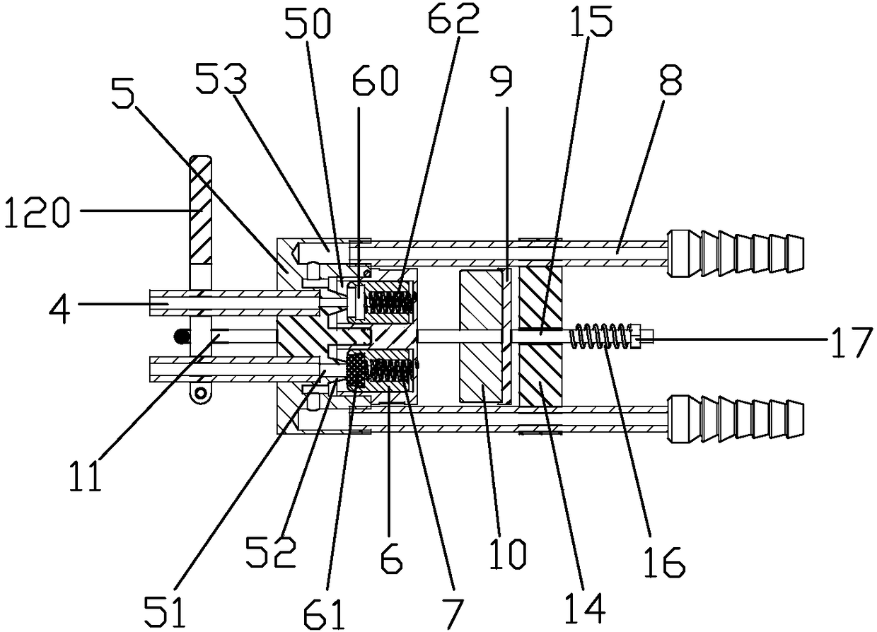
[0031] Embodiment 2: as figure 1 , Figure 4 and Figure 5 A magnetically controlled energy-saving welding torch structure is shown, including a connecting seat 1 and an air jet pipe 2, one end of the air jet pipe is connected to the connecting seat, the other end of the air jet pipe is provided with a welding tip 3, and the connecting seat is provided with two parallel connecting Pipe 4, two connecting pipes communicate with the jet pipe through the flow channel in the connecting seat; the inlet end of the connecting pipe 4 is provided with a valve seat 5, and the valve seat is provided with two independent valve chambers 50, and the front end of the valve seat is provided with There are two outlet air passages 51 correspondingly connected with the valve chamber, the inner end of the outlet air passage extends into the valve chamber to form a tapered convex ring 52, two connecting pipes are connected with the outer ends of the outlet air passage one by one, There is a spool...

Embodiment 3

[0035] Embodiment 3: as figure 1 , Figure 7 and Figure 8 As shown, the difference between embodiment 3 and embodiment 1 is that: the air intake channel is located on the left and right sides of the valve seat, and the two intake pipes are respectively connected to the air intake channels on the left and right sides of the valve seat, and the rest of the structure is the same as that of embodiment 1. The structure in is consistent.

[0036] The forward movement and reset of the permanent magnet is realized by the permanent magnet forward drive mechanism and the permanent magnet reset mechanism. When the permanent magnet moves forward, it is close to the valve core, and the valve core is attracted by the magnetic force to move backward. The outlet flow channel is opened, and oxygen and gas pass through the outlet flow. When it needs to be closed, the permanent magnet moves backward away from the valve core, the magnetic force decreases, the pressure of the compression spring...


PUM


Abstract

The invention relates to the technical field of welding guns, and discloses a magnetic control type energy-saving welding gun structure. The magnetic control type energy-saving welding gun structure comprises a connecting base and a gas ejector pipe; two parallel connecting pipes are arranged on the connecting base; a valve seat is arranged at the gas inlet ends of the connecting pipes; two independent valve cavities are formed in the valve seat; two gas outlet runners communicating with the valve cavities in a one-to-one correspondence manner are formed in the front end of the valve seat; thetwo connecting pipes are connected to the outer ends of the gas outlet channels in a one-to-one correspondence manner; valve elements made of ferromagnets are arranged in the valve cavities; pressuresprings are arranged at the rear ends of the valve elements; two parallel gas inlet pipes capable of communicating with the valve cavities are further arranged on the valve seat; a sliding base is arranged between the two gas inlet pipes; permanent magnets corresponding to the valve elements in a one-to-one manner are arranged on the sliding base; a pull rod is arranged on the sliding base; a permanent magnet forward-moving driving mechanism is arranged on the pull rod; a permanent magnet reset mechanism is arranged between the two gas inlet pipes; and a shell is arranged on the outer side ofthe valve seat. According to the magnetic control type energy-saving welding gun structure, the gas on-off state control response is fast, gas waste can be reduced, and gas energy can be saved.

Description

technical field [0001] The invention relates to the technical field of welding torches, in particular to a magnetically controlled energy-saving welding torch structure. Background technique [0002] A welding torch is a tool used for gas welding, shaped like a gun, with a nozzle at the front end, which emits a high-temperature flame as a heat source. Since the welding operation is usually intermittent, the working state of the welding torch is also intermittent. The traditional welding torch itself has its own regulating valve to control the gas. The process is: first, when the work starts, open the regulating valves for oxygen and gas respectively, Ignite the welding torch to generate flame; secondly, use the oxygen and gas regulating valve to adjust the flame required for the work; thirdly, when the work is over, close the combustible gas and oxygen regulating valve respectively, and the flame goes out. When the welding torch is working intermittently, the adjustment val...

Claims


Application Information

Patent Timeline
IPC IPC(8): B23K5/00F16K31/08F16K11/044
CPCB23K5/00F16K11/044F16K31/0627F16K31/08
Inventor 薛军弟
Owner 上海晶珊电子科技有限公司
Why Eureka
Try Eureka