
Robot laser cutting device of automobile body sheet metal part

A car body and cutting device technology, applied in auxiliary devices, laser welding equipment, welding/cutting auxiliary equipment, etc., can solve the problems of increasing production cycle, expensive equipment, increasing the difficulty of forming and trimming, etc., to improve efficiency Effect

Inactive Publication Date: 2018-06-29
TIANJIN MASITE BODYWORK EQUIP TECH CO LTD
View PDF0 Cites 0 Cited by
  • Summary
  • Abstract
  • Description
  • Claims
  • Application Information

AI Technical Summary

Problems solved by technology

Many of the sheet metal parts of the automobile body require laser cutting to complete the cutting of the profile and the cutting of the hole. Increased difficulty in forming and trimming
The operation and cost of molds and traditional cutting equipment have great limitations. Often a complex surface requires several sequences of molds to complete, which increases the production cycle and wastes costs.
Traditional planar laser cutting equipment is aimed at cutting two-dimensional planes, and cannot perform high-precision cutting on three-dimensional curved surface parts. Some large-scale three-dimensional laser cutting equipment needs to be imported from abroad. The equipment is expensive and the cutting range is very limited.

Method used


Image

  • Robot laser cutting device of automobile body sheet metal part
  • Robot laser cutting device of automobile body sheet metal part
  • Robot laser cutting device of automobile body sheet metal part

Examples


Embodiment Construction

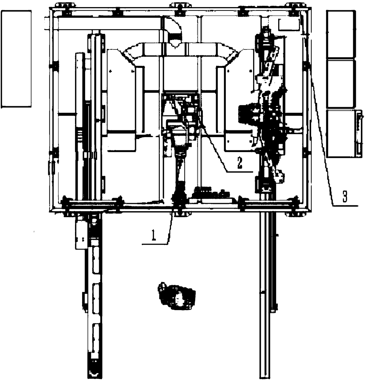
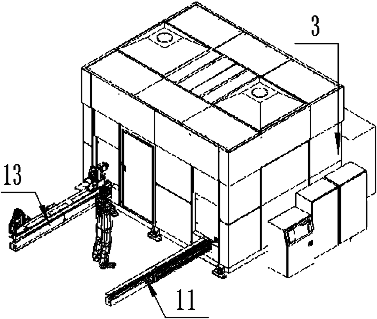
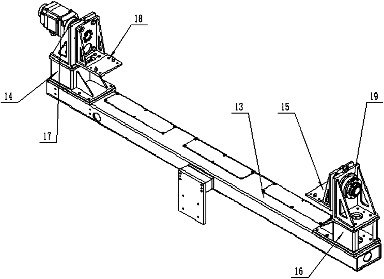
[0015] The present invention will be described in detail below with reference to the drawings, such as Figure 1-4 As shown, it includes an industrial six-axis robot (1), a laser processing head (2), a set of fixture mechanisms, a set of sliding mechanisms, a set of turning mechanisms and a peripheral wall (3), the industrial six-axis robot (1), The laser processing head (2), a set of fixture mechanisms, a set of sliding mechanisms and a set of turning mechanisms are all located in the peripheral wall, and the laser processing head (2) is installed on the turntable of the sixth axis of the industrial six-axis robot (1) The clamping mechanism is located above the turning mechanism, the turning mechanism is located on the sliding mechanism, and the clamping mechanism is composed of a bracket (4), an air cylinder (5) installed on the outer and lower surface of the bracket (4), and a bracket (4). ) The outer upper surface, and close to the limit tables (6) at both ends, the fixed a...


PUM

PropertyMeasurementUnit
angleaaaaaaaaaa

Abstract

The invention discloses a robot laser cutting device of an automobile body sheet metal part. The robot laser cutting device comprises an industrial six-axis robot, a laser processing head, a set of clamp mechanism, a set of sliding mechanism, a set of turnover mechanism and a periphery wall. The industrial six-axis robot, the laser processing head, the set of clamp mechanism, the set of sliding mechanism and the set of turnover mechanism are all located in the periphery wall. The laser processing head is mounted on a rotary disc of a sixth axis of the industrial six-axis robot. The clamp mechanism is located above the turnover mechanism. The turnover mechanism is located on the sliding mechanism. The robot laser cutting device has the advantages of being simple in structure and high in practicality.

Description

Technical field [0001] The invention relates to the field of automobiles, in particular to a robot laser cutting device for automobile body sheet metal parts. Background technique [0002] Laser cutting is the most important application technology in the laser processing industry. Because of its many characteristics, it has been widely used in industries such as automobiles, rolling stock manufacturing, aviation, chemical, light power, electrical and electronics, petroleum and metallurgy. Compared with other cutting methods, the biggest difference between laser cutting is that it has the characteristics of high speed, high precision, and high adaptability. At the same time, it also has the advantages of fine slitting, small heat-affected zone, good cutting surface quality, no noise during cutting, good verticality of slit edges, smooth cutting edges, and easy automatic control of the cutting process. Many of the sheet metal parts of the car body require laser cutting to complete...

Claims


Application Information

Patent Timeline
Patent Type & Authority Applications(China)
IPC IPC(8): B23K26/38B23K26/70B23K26/08B23K37/04
CPCB23K26/0823B23K26/38B23K37/0435B23K26/702
Inventor 郑松刚
Owner TIANJIN MASITE BODYWORK EQUIP TECH CO LTD
Learn More