Automatic steel strip end cap sleeving machine

A steel bar and automatic technology, applied in metal processing equipment, metal processing, manufacturing tools, etc., can solve problems such as low efficiency and high labor intensity, and achieve the effect of liberating manpower, reducing labor costs, and continuous automatic installation

Active Publication Date: 2018-06-29
徐锋
View PDF10 Cites 7 Cited by
  • Summary
  • Abstract
  • Description
  • Claims
  • Application Information

AI Technical Summary

Problems solved by technology

[0003] In traditional production, it is necessary to manually set the steel rods. The method of manually setting the end caps on the steel rods requires continuous human action on the one hand, resulting in a problem of high labor intensity. On the other hand, the efficiency of manual fitting is relatively low.
There is no fully automatic equipment on the market that can completely replace manual labor

Method used


Image

  • Automatic steel strip end cap sleeving machine
  • Automatic steel strip end cap sleeving machine
  • Automatic steel strip end cap sleeving machine

Examples


Embodiment Construction

[0039] The present invention will be described in detail below in conjunction with the accompanying drawings and embodiments.

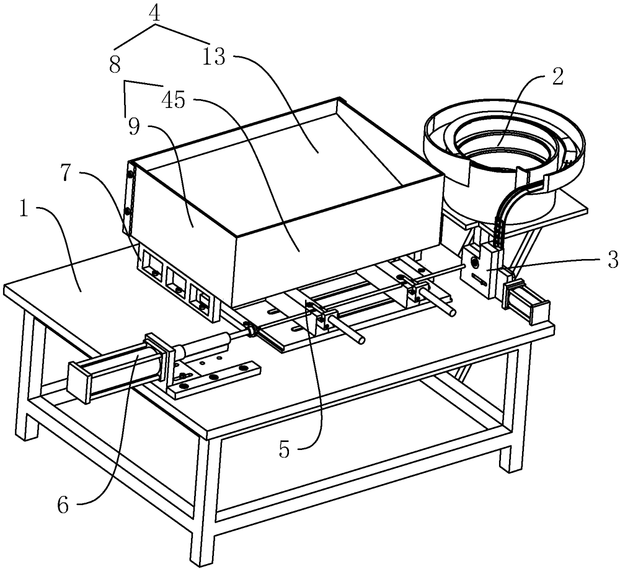
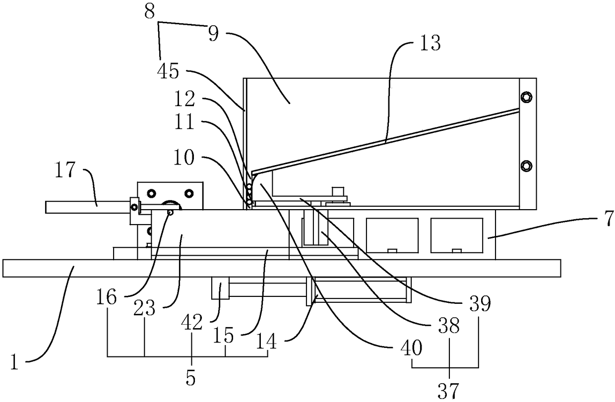
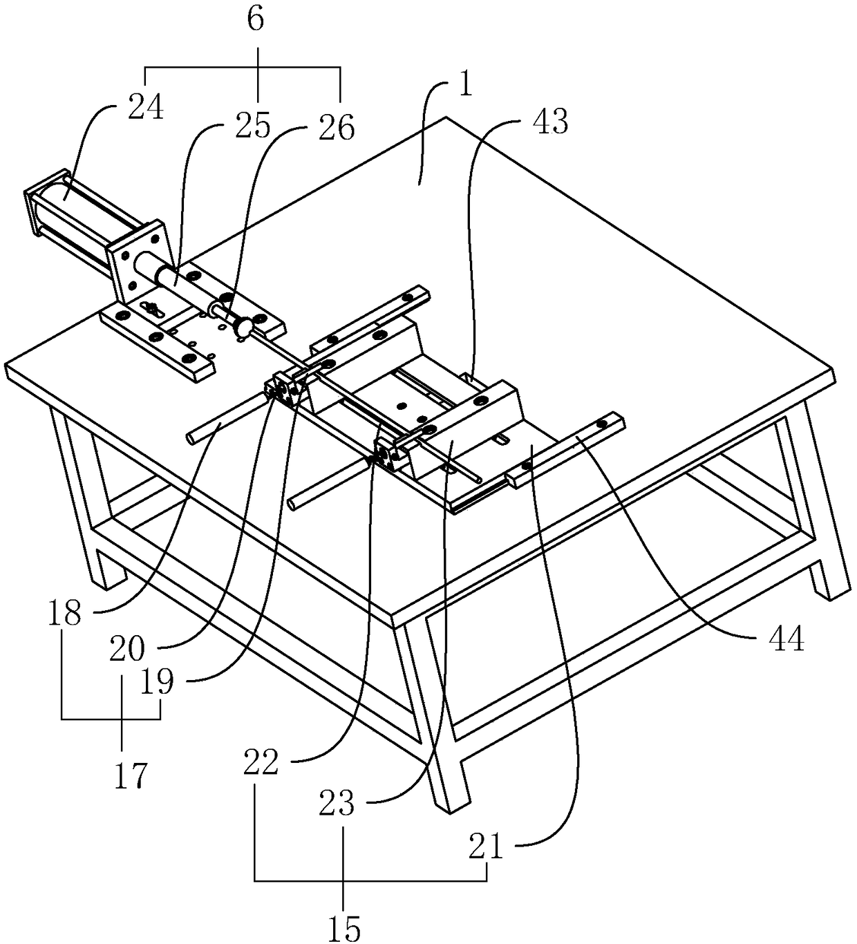
[0040] A steel bar end cap automatic sleeve machine, such as figure 1 As shown, it includes a frame 1 and a vibrating tray 2 placed on one side of the frame 1, a clamping assembly 3 connected to the discharge end of the vibrating tray 2 and used to clamp the end cap, arranged on the frame 1 and supplied with steel The feeding mechanism 4 arranged in strips, the feeding assembly 5 that is arranged under the feeding mechanism 4 and pushes out a certain steel bar, and the driving mechanism 6 that is arranged on the frame 1 and is collinear with the lower material level of the feeding assembly 5.

[0041] Such as figure 1 As shown, the end caps are placed in the vibrating tray 2, and the end caps are sent to the clamping assembly 3 through the discharge end by the vibrating tray 2, and one of the end caps is clamped by the clamping assembly 3, and the ma...


PUM


Abstract

The invention discloses an automatic steel strip end cap sleeving machine, and aims at solving the problems that during traditional manual steel strip and end cap installation, efficiency is low, andmanpower is wasted. According to the technical scheme, the automatic steel strip end cap sleeving machine is characterized by comprising a rack, a vibration material disc arranged on one side of the rack, a clamping assembly connected to the discharging end of the vibration material disc and used for clamping an end cap, a feeding mechanism arranged on the rack and used for arranging steel strips,a conveying assembly arranged below the feeding mechanism and used for pushing one steel strip out, and a drive mechanism which is arranged on the rack and is collinear to the discharging position ofthe conveying assembly. According to the automatic steel strip end cap sleeving machine, through automatic steel strip and end cap installation, manpower is greatly liberated, labor force consumptionis reduced, and the installing efficiency is improved.

Description

technical field [0001] The invention relates to processing equipment for luggage accessories, more specifically, it relates to an automatic sleeve-setting machine for steel bar end caps. Background technique [0002] The suitcase is a box that is used to place articles when going out. The suitcase includes a shell made of ABS material, and steel bars are usually arranged in the shell to improve the strength of the suitcase. However, in order to avoid the end of the steel bar from penetrating the shell, An end cap made of plastic needs to be set on the end of the steel bar. One end of the end cap is set on the end of the steel bar, and the other end is pressed against the inner wall of the shell, and the side of the end cap close to the inner wall of the shell is flat. Set, so that the contact area between the end cap and the luggage shell is increased, and the end of the steel bar is prevented from penetrating the shell. [0003] In traditional production, it is necessary t...

Claims


Application Information

Patent Timeline
Patent Type & Authority Applications(China)
IPC IPC(8): B23P19/00
CPCB23P19/00B23P19/001
Inventor 徐锋徐云光
Owner 徐锋
Why Eureka
Try Eureka