Polished Dust Hood

A dust hood, dry polishing technology, used in grinding/polishing equipment, grinding/polishing safety devices, metal processing equipment, etc., can solve the problems of dust reflux and unsatisfactory dust collection efficiency, and achieve airflow flow Smooth, anti-regurgitation, combined with a gentle effect

Active Publication Date: 2019-08-20
玉环太平洋机械有限公司
View PDF13 Cites 0 Cited by
  • Summary
  • Abstract
  • Description
  • Claims
  • Application Information

AI Technical Summary

Problems solved by technology

[0005] There is a small part of the dust backflow phenomenon in the existing dust collection hoods of various structures, which in turn causes a small part of the dust to flow out from the polishing control port, that is, there is a problem that the dust collection efficiency cannot meet the requirements of some users

Method used


Image

  • Polished Dust Hood
  • Polished Dust Hood
  • Polished Dust Hood

Examples


Embodiment 1

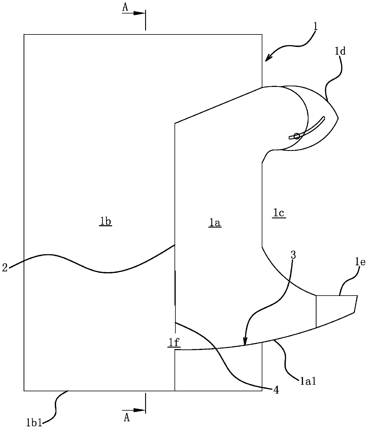
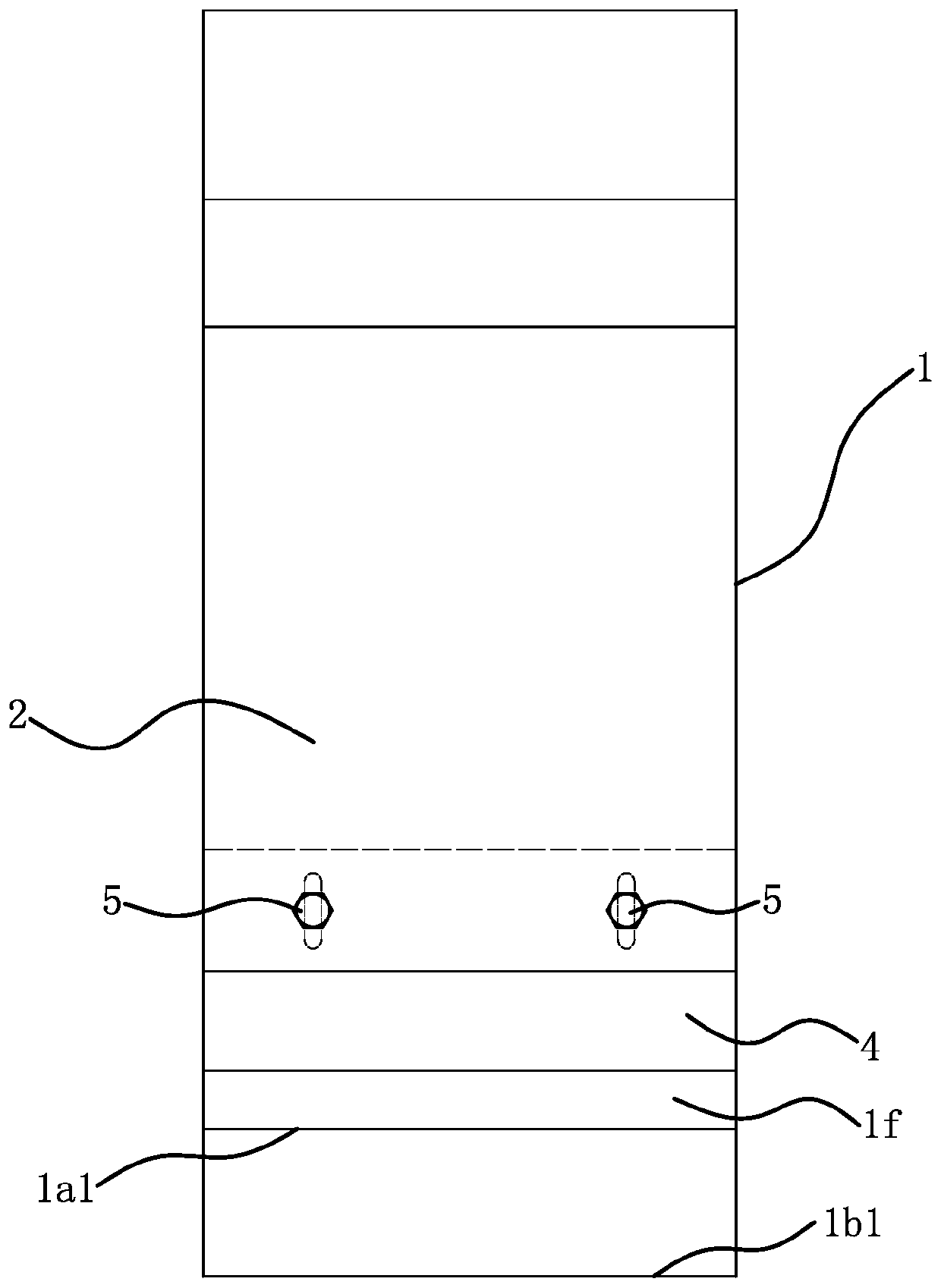
[0024] Such as figure 1 and figure 2 As shown, the polishing dust collection cover includes a cover body 1 and a partition 2, and the cover body 1 is in the shape of a box, that is, roughly in the shape of a cuboid.

[0025] The bottom of the partition 2 is arranged vertically, and the two side edges and the top edge of the partition 2 are sealed and fixedly connected with the wall of the cover body 1, thereby dividing the inner cavity of the cover body 1 into a grinding operation chamber 1a and a dust settlement chamber 1b, The grinding operation chamber 1a is located on the front side of the dust settling chamber 1b. There is a polishing operation port 1c on the front side wall of the polishing operation chamber 1a. In order to ensure the dust collection efficiency, there is a brim part 1d above the polishing operation port 1c, and a forehead part 1e below the polishing operation port 1c; the top of the partition 2 can be opposite The bottom is inclined or the top of the ...

Embodiment 2

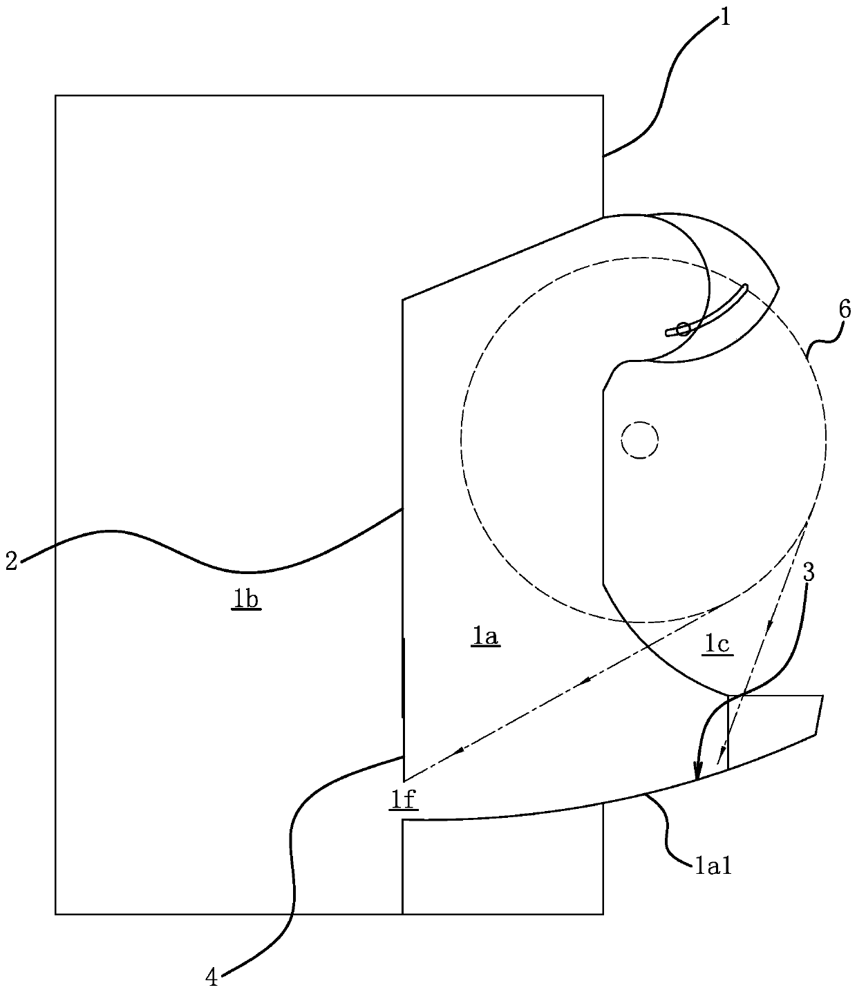
[0032] The structure and principle of this embodiment are basically the same as that of Embodiment 1, and the basic similarities will not be redundantly described, and only the differences will be described, and the differences are as follows: Figure 6 As shown, the bottom plate 1a1 of the grinding operation chamber 1a is arranged obliquely and has a non-arc shape; the bottom plate 1a1 of the grinding operation chamber 1a does not form the wind guide surface 3; Can be water. The air guide surface 3 is formed by the gap between the top surface of the liquid medium 9 and the lower edge of the dividing plate 2 by the air flow; that is, the fan 7 runs in the cover body 1 to form an air flow from the polishing control port 1c to the air vent, and the liquid level of the liquid medium 9 Under the action of the airflow, the arc-shaped wind guiding surface 3 is naturally formed.

[0033]By adjusting the height of the shutter 4 and the liquid level of the liquid medium 9, the positio...

Embodiment 3

[0036] The structure and principle of this embodiment are basically the same as that of Embodiment 2, and the basic similarities will not be redundantly described, and only the differences will be described. The differences are as follows: Figure 7 As shown, a horizontally arranged rotating shaft 10 is arranged in the dust settling chamber 1b, and the rotating shaft 10 is connected to the side wall of the dust settling chamber 1b through bearing rotation. There are multiple blades 11 installed on it, and when the rotating shaft 10 rotates, the blades 11 stir the liquid medium 9 to generate water spray and water mist, which can be integrated into the airflow generated by the fan, and when the airflow contains dust, the water spray and water mist The combination of mist and dust realizes wet dust removal.


PUM


Abstract

The invention belongs to the technical field of operation, provides a polishing dust hood and solves the problem of backflow of a small part of dust in use of existing dust hoods. The polishing dust hood comprises a box shaped hood body, a partition plate for partitioning an inner cavity of the hood body into a polishing operating cavity and a dust settling cavity is fixed in the hood body, the polishing operating cavity is positioned on the front side of the dust settling cavity, the front side wall of the polishing operating cavity is provided with a polishing control port, the dust settlingcavity is provided with a vent port, and the bottom of the polishing operating cavity is provided with an arc air guide face below the polishing control port. The rear end of the air guide face extends to a position under the partition plate, an air passage is formed between the lower edge of the partition plate and the air guide face, and a bottom plate of the dust settling cavity is lower thanthe air guide face. The polishing dust hood has advantages that by redesign of an internal structure of the hood body, smoothness in air flowing and less proneness to backflow generation are realized;in addition, dust airflow and airflow generated by a fan are combined more gently, namely the dust airflow can be more easily blended into the airflow generated by the fan.

Description

technical field [0001] The invention belongs to the field of operation technology, and relates to grinding and polishing, in particular to a polishing dust collection cover. Background technique [0002] Polishing is a process of reducing the surface roughness of an object using physical machinery or chemicals. The surface of the polished workpiece is smooth and has a good reflection effect. [0003] Polishing will generate a lot of dust and the polishing wheel will produce debris. Therefore, it is necessary to install a dust collection cover outside the polishing wheel during the operation. The dust collection cover is connected with the dust collector and the fan to avoid dust diffusion as much as possible and ensure the cleanliness of the workshop environment. [0004] For this reason, the inventor has designed a large amount of dust collection covers successively, as the dust collection cover of a kind of polishing machine (authorization announcement number CN201455809U...

Claims


Application Information

Patent Timeline
Patent Type & Authority Patents(China)
IPC IPC(8): B24B55/06
Inventor 陈美青
Owner 玉环太平洋机械有限公司
Why Eureka
Try Eureka