Corrugated board perforating machine for printing factory

A corrugated cardboard and punching machine technology, applied in the field of punching machines, can solve the problems of slow punching speed, time-consuming and labor-intensive problems

Inactive Publication Date: 2018-06-29
郑文平
View PDF11 Cites 13 Cited by
  • Summary
  • Abstract
  • Description
  • Claims
  • Application Information

AI Technical Summary

Problems solved by technology

[0005] In order to overcome the shortcomings of manual punching of corrugated paper, which is time-consuming and laborious, the punching speed is slow, and sundries will remain after punching, which will affect the environment, the technical problem to be sol

Method used


Image

  • Corrugated board perforating machine for printing factory
  • Corrugated board perforating machine for printing factory
  • Corrugated board perforating machine for printing factory

Examples


Embodiment 1

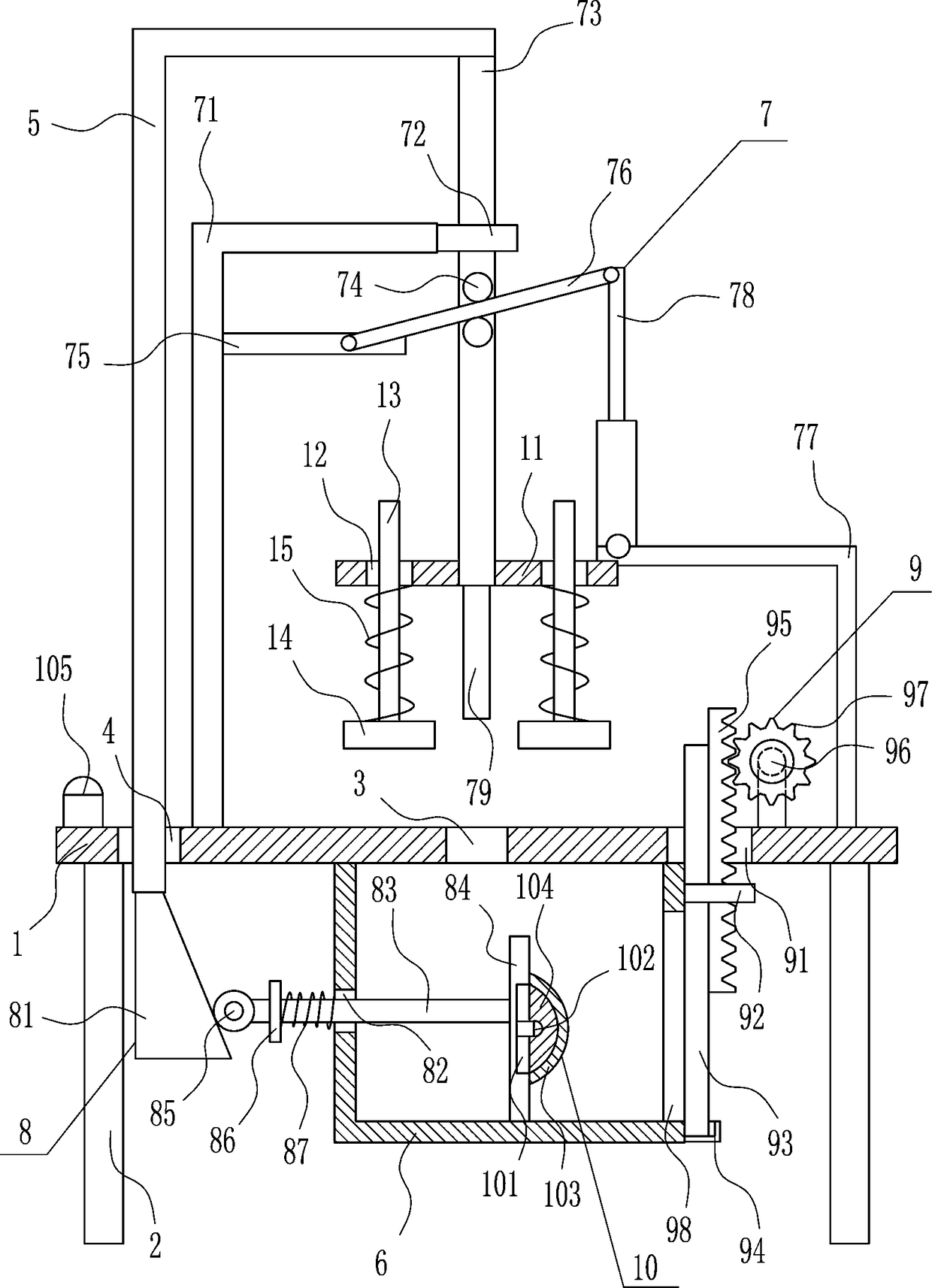
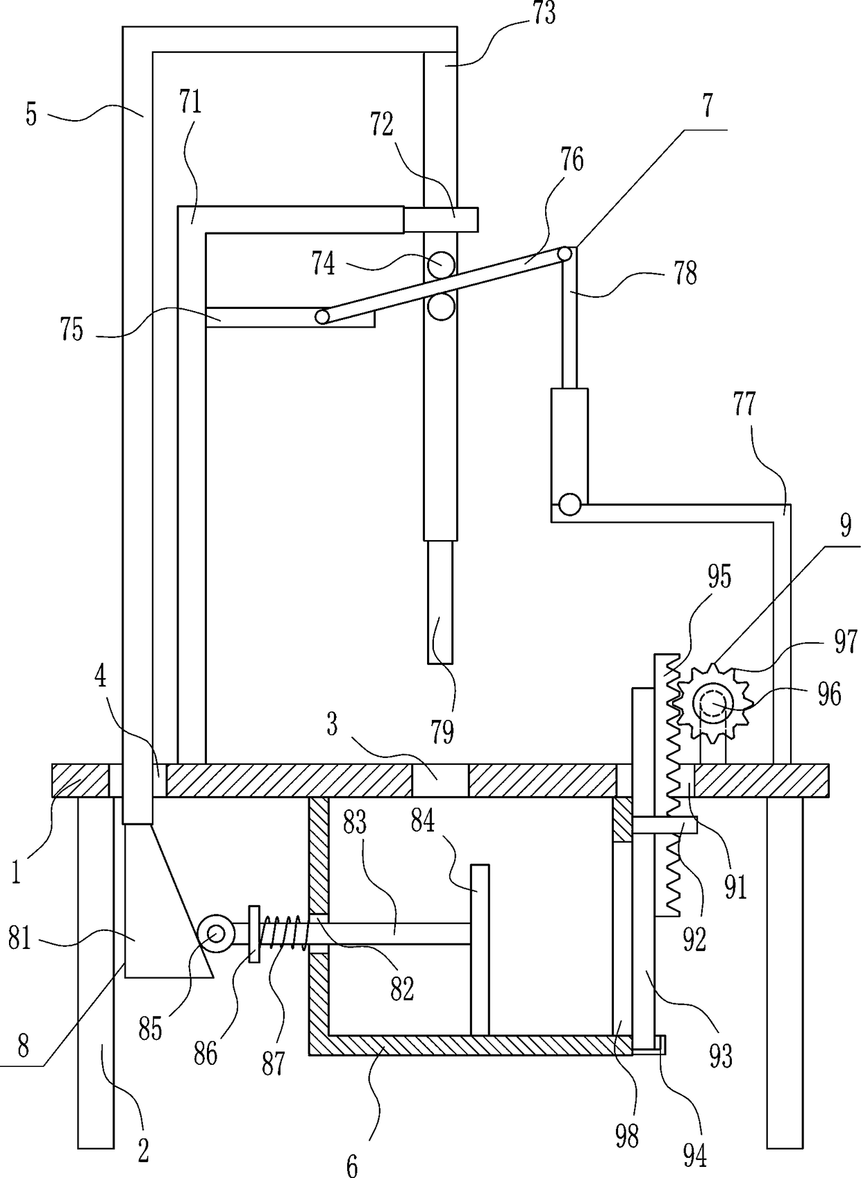
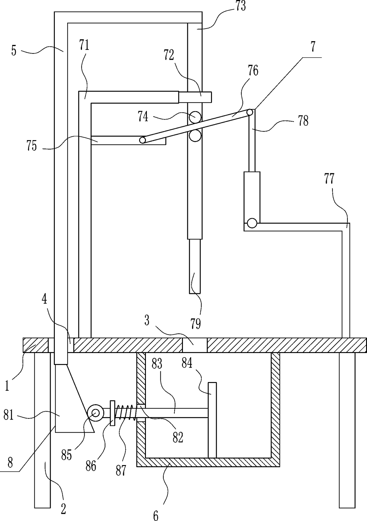
[0035] A corrugated cardboard punching machine for a printing house, such as Figure 1-5 As shown, it includes a placement board 1, legs 2, the first 7-type board 5, a collection frame 6, a punching device 7 and a compression device 8, and the bottom of the placement board 1 is symmetrically installed with legs 2 on both sides. There is a first through hole 3 in the middle of the board 1, a second through hole 4 is opened in the left part of the placement board 1, a first 7-type board 5 is arranged in the second through hole 4, and a punching device is provided on the top right side of the placement board 1 7. The punching part of the punching device 7 is located directly above the first through hole 3. The punching device 7 is connected to the right side of the top inside the first 7-type plate 5. A collection frame 6 is installed in the middle of the bottom of the placement plate 1. The collection frame 6 Located below the first through hole 3 , a compression device 8 is pro...

Embodiment 2

[0037] A corrugated cardboard punching machine for a printing house, such as Figure 1-5 As shown, it includes a placement board 1, legs 2, the first 7-type board 5, a collection frame 6, a punching device 7 and a compression device 8, and the bottom of the placement board 1 is symmetrically installed with legs 2 on both sides. There is a first through hole 3 in the middle of the board 1, a second through hole 4 is opened in the left part of the placement board 1, a first 7-type board 5 is arranged in the second through hole 4, and a punching device is provided on the top right side of the placement board 1 7. The punching part of the punching device 7 is located directly above the first through hole 3. The punching device 7 is connected to the right side of the top inside the first 7-type plate 5. A collection frame 6 is installed in the middle of the bottom of the placement plate 1. The collection frame 6 Located below the first through hole 3 , a compression device 8 is pro...

Embodiment 3

[0040] A corrugated cardboard punching machine for a printing house, such as Figure 1-5 As shown, it includes a placement board 1, legs 2, the first 7-type board 5, a collection frame 6, a punching device 7 and a compression device 8, and the bottom of the placement board 1 is symmetrically installed with legs 2 on both sides. There is a first through hole 3 in the middle of the board 1, a second through hole 4 is opened in the left part of the placement board 1, a first 7-type board 5 is arranged in the second through hole 4, and a punching device is provided on the top right side of the placement board 1 7. The punching part of the punching device 7 is located directly above the first through hole 3. The punching device 7 is connected to the right side of the top inside the first 7-type plate 5. A collection frame 6 is installed in the middle of the bottom of the placement plate 1. The collection frame 6 Located below the first through hole 3 , a compression device 8 is pro...


PUM


Abstract

The invention relates to a perforating machine, in particular to a corrugated board perforating machine for a printing factory. The corrugated board perforating machine for the printing factory has the advantages of being time-saving and labor-saving, high in perforating speed and capable of compressing sundries left after perforation without influencing the surrounding environment. The corrugatedboard perforating machine for the printing factory comprises a containing plate and the like, wherein supporting legs are symmetrically mounted on the left side and the right side of the bottom of the containing plate, a first through hole is formed in the middle of the containing plate, and a second through hole is formed in the left part of the containing plate; and a first 7-shaped plate is arranged in the second through hole, a perforating device is arranged on the right side of the top of the containing plate, and a perforating part of the perforating device is located right above the first through hole. According to the corrugated board perforating machine for the printing factory, through a compression device, the sundries falling during perforating can be compressed, so that people can conveniently process the sundries, and the advantages of being time-saving and labor-saving and high in perforating speed are realized.

Description

technical field [0001] The invention relates to a punching machine, in particular to a punching machine for corrugated cardboard used in a printing factory. Background technique [0002] Printing is a technology that transfers the ink to the surface of paper, fabric, plastic, leather and other materials through plate making, ink application, and pressurization to copy the contents of the original manuscript in batches. Printing is the process of transferring the approved printing plate to the substrate through printing machinery and special ink. [0003] In order to make the corrugated paper boxes made of corrugated paper ventilated, the corrugated paper will be perforated, but when the corrugated paper is manually perforated, it is time-consuming and laborious, the perforation speed is slow, and debris will remain after perforation, which will affect the environment. Therefore, it is urgent It is necessary to develop a corrugated cardboard punching machine for printing pla...

Claims


Application Information

Patent Timeline
IPC IPC(8): B26F1/16B26D5/12B26D7/18B30B9/30
CPCB26D5/12B26D7/18B26F1/16B30B9/30
Inventor 李瑞光郑文平
Owner 郑文平
Why Eureka
Try Eureka