
Injection mold for producing automobile part

A technology for auto parts and injection molds, applied in the field of injection molds, can solve problems such as plastic blocking of air intakes, and achieve the effect of increasing maintenance costs

Inactive Publication Date: 2018-06-29
CHONGQING YINSHENG MOLD
View PDF1 Cites 1 Cited by
  • Summary
  • Abstract
  • Description
  • Claims
  • Application Information

AI Technical Summary

Problems solved by technology

[0003] The purpose of the present invention is to improve an injection mold for the production of auto parts to solve the technical problem that the plastic will block the air outlet during injection molding

Method used


Image

  • Injection mold for producing automobile part
  • Injection mold for producing automobile part
  • Injection mold for producing automobile part

Examples


Embodiment Construction

[0022] The present invention will be described in further detail below by means of specific embodiments:

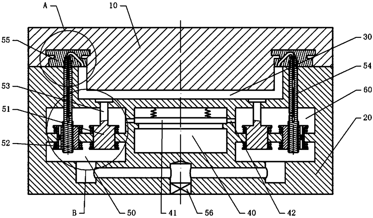
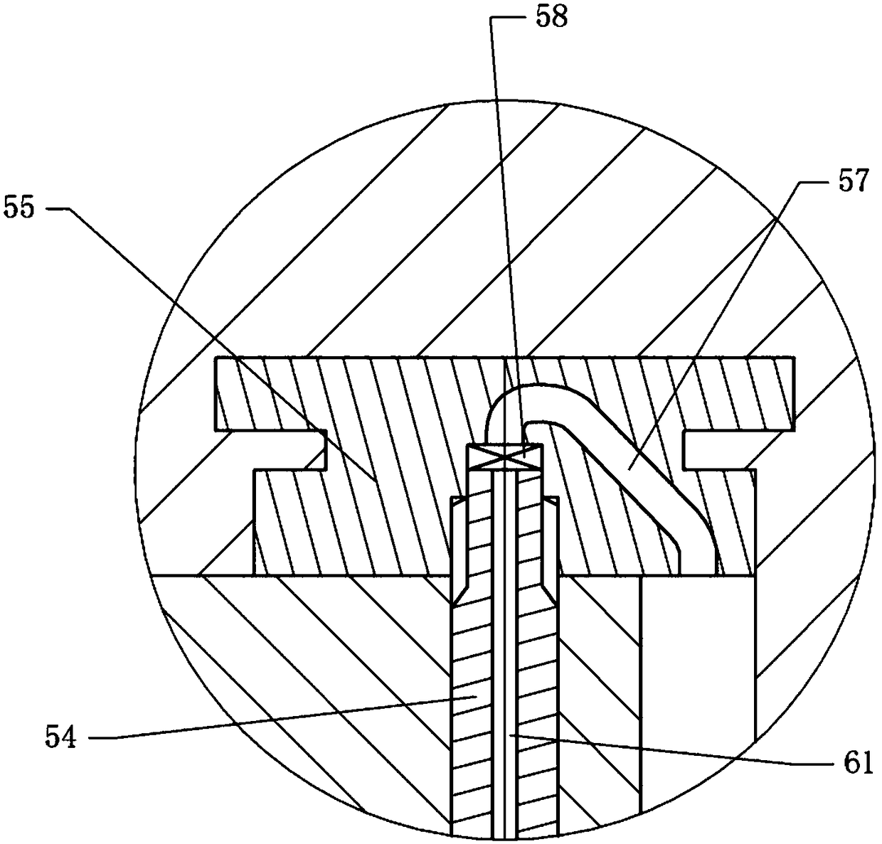
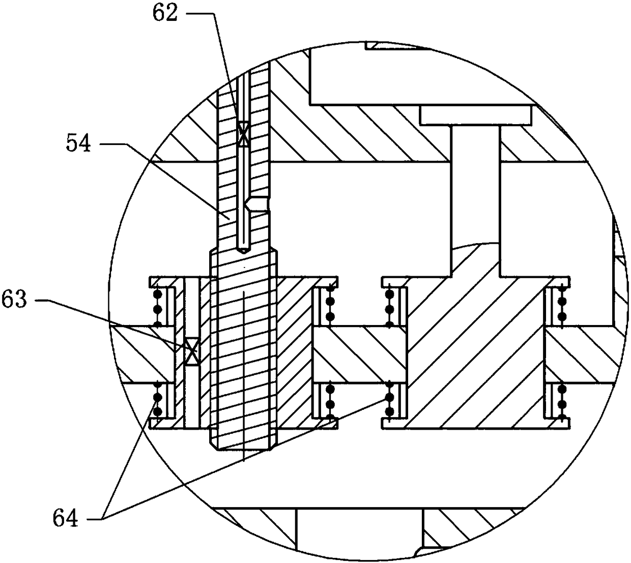
[0023] The reference signs in the drawings of the description include: upper mold 10, lower mold 20, mold cavity 30, preheating cavity 40, block 41, opening 42, air chamber 50, second piston 51, first piston 52, ejector rod 53. Revolving shaft 54, turning block 55, stop valve 56, air inlet 57, quick connector 58, vacuum chamber 60, air passage 61, second one-way valve 62, first one-way valve 63, balance spring 64,

[0024] The embodiment is basically as figure 1 , figure 2 , image 3 Shown:

[0025] The injection mold for the production of auto parts of the present embodiment comprises an upper mold 10 and a lower mold 20, the upper mold 10 is a convex mold, and the lower mold 20 is a concave mold. After the upper mold 10 and the lower mold 20 are fastened, the upper mold 10 and the lower mold A mold cavity 30 is formed between 20, and an injection channel is provide...


PUM


Abstract

The application relates to an injection mold, and particularly discloses an injection mold for producing an automobile part. The injection mold comprises an upper die and a lower die, wherein a vacuumcavity and a regulating mechanism are formed and arranged in the lower die; the regulating mechanism comprises an air chamber, a first piston, a second piston and a rotating block; the first piston and the second piston are used for closing the air chamber; two ends of each of the first piston and the second piston are located in the vacuum cavity and the air chamber respectively; a first check valve is arranged in the first piston; the second piston is fixedly provided with an ejector rod stretching into a die cavity; the rotating block is provided with an air inlet; a rotating shaft is rotationally connected into the lower die; an air passage communicated with the vacuum cavity is formed in the rotating shaft; the air passage is communicated with the air inlet through a quick connector;a second check valve is arranged in the air passage; one end of the rotating shaft is connected with the rotating block through a spline; the other end of the rotating shaft spirally cooperates withthe first piston; a preheating cavity is formed in the lower die below the die cavity; the side wall of the preheating cavity is provided with an opening which can be communicated with the vacuum cavity; a blocking block is arranged in the preheating cavity. During injection molding, the air inlet is not opposite to the die cavity, and thus, plastic can be prevented from blocking the air inlet.

Description

technical field [0001] The invention relates to an injection mold, in particular to an injection mold for auto parts production. Background technique [0002] Injection mold is a tool for producing plastic products; it is also a tool for giving plastic products complete structure and precise dimensions. Injection molding is a processing method used in the mass production of certain complex-shaped parts. Specifically, it refers to injecting the heated and melted material into the mold cavity by high pressure, and after cooling and solidifying, a molded product is obtained. In the existing injection mold, when the product is formed, because there is air in the forming groove, it is easy to form air bubbles during the forming process or the shape of the product is uneven due to the air pressure. The existing method for solving the air hole defect in the injection molded part is to vacuumize the mold cavity of the mold before injection molding to reduce the air content in the ...

Claims


Application Information

Patent Timeline
Patent Type & Authority Applications(China)
IPC IPC(8): B29C45/34B29C45/17
CPCB29C45/34B29C45/17
Inventor 邱建华
Owner CHONGQING YINSHENG MOLD
Learn More