Composite laminated plate manufacturing mold

A technology of composite material layer and mould, which can be applied to household appliances, other household appliances, household components, etc., and can solve problems such as poor sealing, inability to obtain products, incomplete infiltration, etc., to facilitate disassembly and maintenance, and improve resin flow performance and improve the surface quality

Inactive Publication Date: 2018-06-29
JILIN UNIV
View PDF8 Cites 3 Cited by
  • Summary
  • Abstract
  • Description
  • Claims
  • Application Information

AI Technical Summary

Problems solved by technology

Composite material manufacturing processes include hand lay-up molding, vacuum bag molding, resin injection molding, vacuum-assisted resin injection molding, etc. Among them, resin injection molding and vacuum-assisted resin injection molding have high requirements on the precision of the mold, and the surface accuracy of the mold and If the sealing is not good, it is easy to cause various defects in the product
[0003] Traditional resin injection molding molds are composed of simple upper and lower molds. The upper and lower molds use grooves or add specific thickness gaskets between the upper and lower molds to control the thickness of the product. However, due to manufacturing accuracy and processing errors, gaskets with too small thickness cannot be made. Thinner products cannot be obtained, and products of ideal thickness cannot be accurately produced, so that specific needs cannot be met
Poor sealing will also lead to defects such as air bubbles and dry spots in the product. Since the mold is generally a steel mold, the temperature of the resin flowing in the steel mold is too low, which will easily cause incomplete infiltration and affect the quality of the product.

Method used


Image

  • Composite laminated plate manufacturing mold
  • Composite laminated plate manufacturing mold
  • Composite laminated plate manufacturing mold

Examples


Embodiment Construction

[0021] The present invention will be described in detail below in conjunction with the accompanying drawings and specific embodiments.

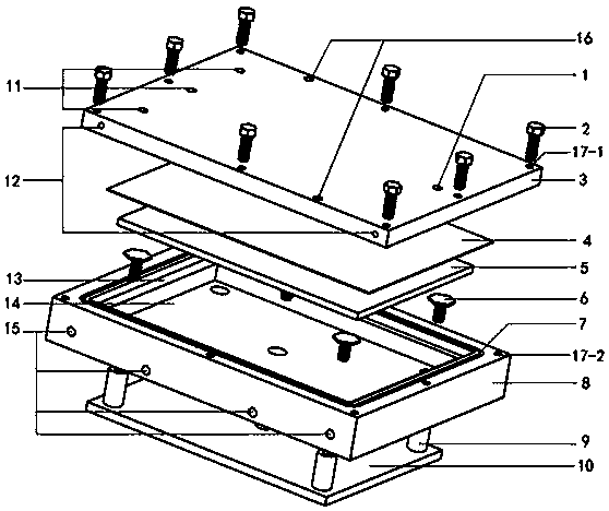
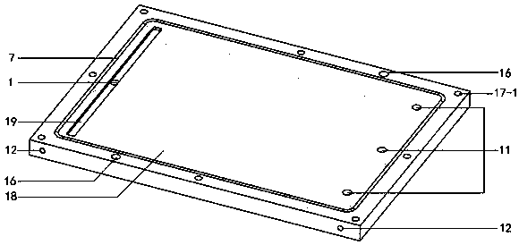
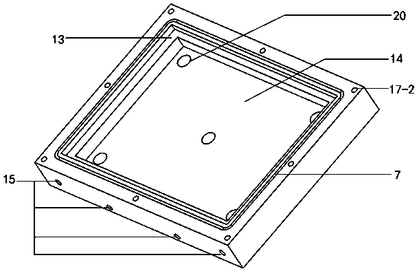
[0022] attached by figure 1 , 2 , 3, 4, 5, 7, and 8 show: a mold with continuously adjustable thickness, including fastening bolt 2, upper mold 3, lower template 4, upper top plate 5, ejector bolt 6, lower mold 8, top Rod 9 and lower top plate 10, a push rod 9 is respectively arranged at the middle position and four top corners of the lower top plate 10, and a push rod hole 20 corresponding to the push rod 9 is provided on the lower mold 8 and set The ejector rod fastening mechanism 21 on the ejector rod hole 20, the ejector rod 9 is set in the ejector rod hole 20 and can move freely in the ejector rod hole 20, and the ejector rod 9 is connected with the lower die by the ejector rod bolt 6 8 connection, the middle of the lower mold 8 is processed with a first stepped groove 13 and a second stepped groove 14, and the edge of the lower mold 8...


PUM


Abstract

The invention discloses a composite laminated plate manufacturing mold. Through the composite laminated plate manufacturing mold, the thickness of laminated plates can be adjusted continuously and accurately. A lower mold surface is provided with stepped grooves. The first stepped groove is internally provided with the lower mold surface. The second stepped groove is provided with an upper top plate. The lower mold surface is provided with ejector pin holes allowing ejector pins to move vertically. The bottom surface of a lower mold is provided with locking devices used for locking push rods.The push rods are provided with graduations. The thickness of a mold cavity can be visually observed through the graduations. The upper and low mold surfaces are provided with sealing grooves for containing seal rings to guarantee the airtightness of the mold cavity. Heating pipes are arranged in an upper mold and the lower mold and can increase the temperature of the mold, so that the fluidity ofresin in the mold cavity is improved. Different thicknesses of laminated plates can be set according to different fiber cloth thicknesses. The fiber volume fraction of products can be controlled by calculating and controlling the content of resin in the laminated plates. Accordingly, the product quality is improved.

Description

technical field [0001] The invention relates to a composite material forming technology, in particular to a composite material laminate production mold whose thickness can be continuously adjusted. Background technique [0002] With the increasing environmental problems, the requirements for automobile exhaust emissions are becoming more and more stringent, and one way to reduce automobile exhaust emissions is to reduce the weight of automobiles. At the same time, an important way to achieve lightweight automobiles is to use new composite materials. Composite material manufacturing processes include hand lay-up molding, vacuum bag molding, resin injection molding, vacuum-assisted resin injection molding, etc. Among them, resin injection molding and vacuum-assisted resin injection molding have high requirements on the precision of the mold, and the surface accuracy of the mold and Poor sealing can easily cause various defects in the product. [0003] Traditional resin inject...

Claims


Application Information

Patent Timeline
Patent Type & Authority Applications(China)
IPC IPC(8): B29C70/48B29C70/54B29C33/00B29L31/30
CPCB29C33/00B29C70/48B29C70/54B29L2031/30
Inventor 马芳武杨猛陈实现支永帅蒲永锋
Owner JILIN UNIV
Why Eureka
Try Eureka