
Road soundproof panel
A technology for sound insulation boards and roads, which is applied in the direction of noise absorption devices and buildings. It can solve problems such as troubles and uneven filling, and achieve the effects of enhancing the sealing effect, satisfying the micro-scale expansion performance, and good sound-absorbing effect.
- Summary
- Abstract
- Description
- Claims
- Application Information
AI Technical Summary
Problems solved by technology
Method used
Image

Examples
Embodiment Construction
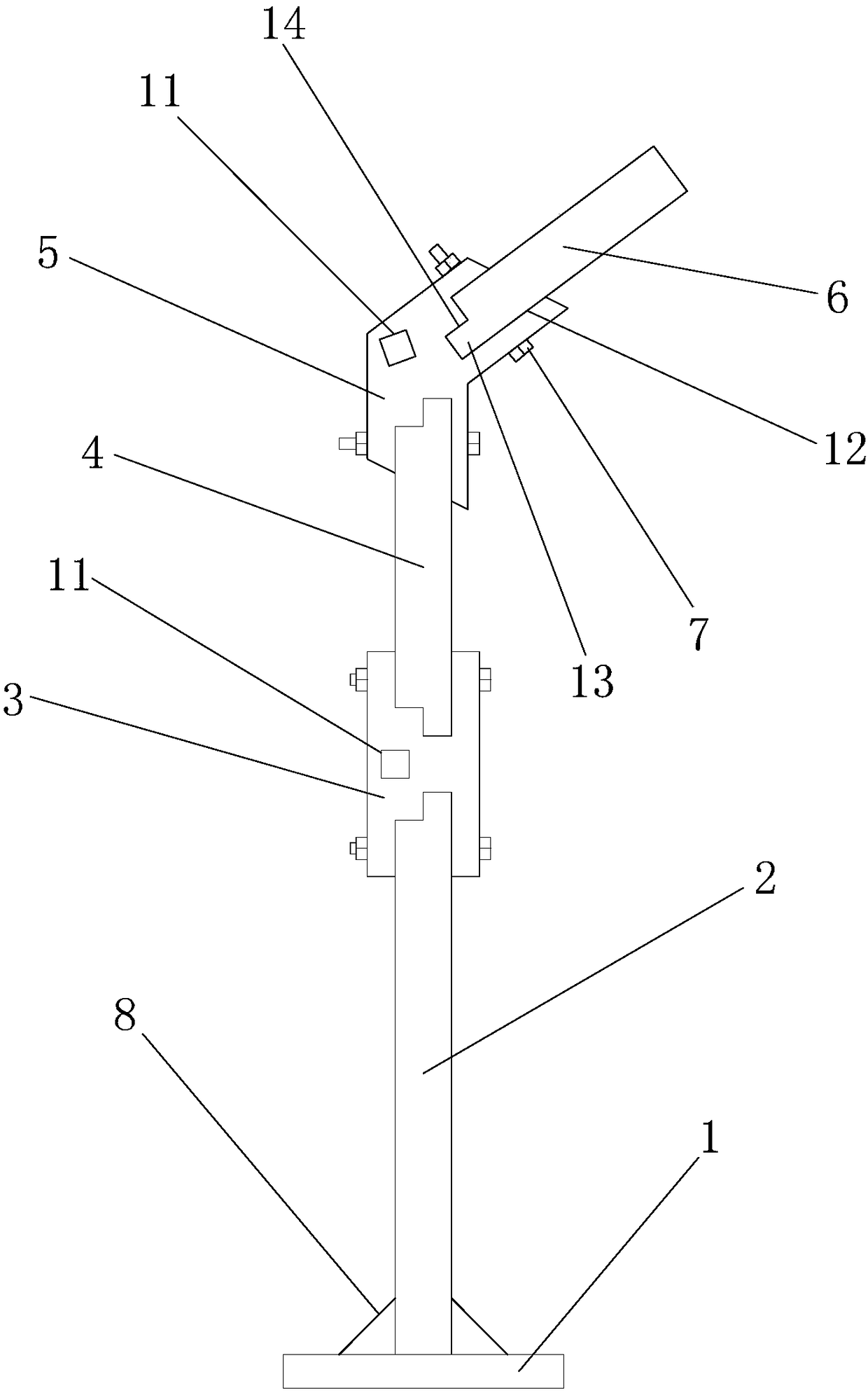
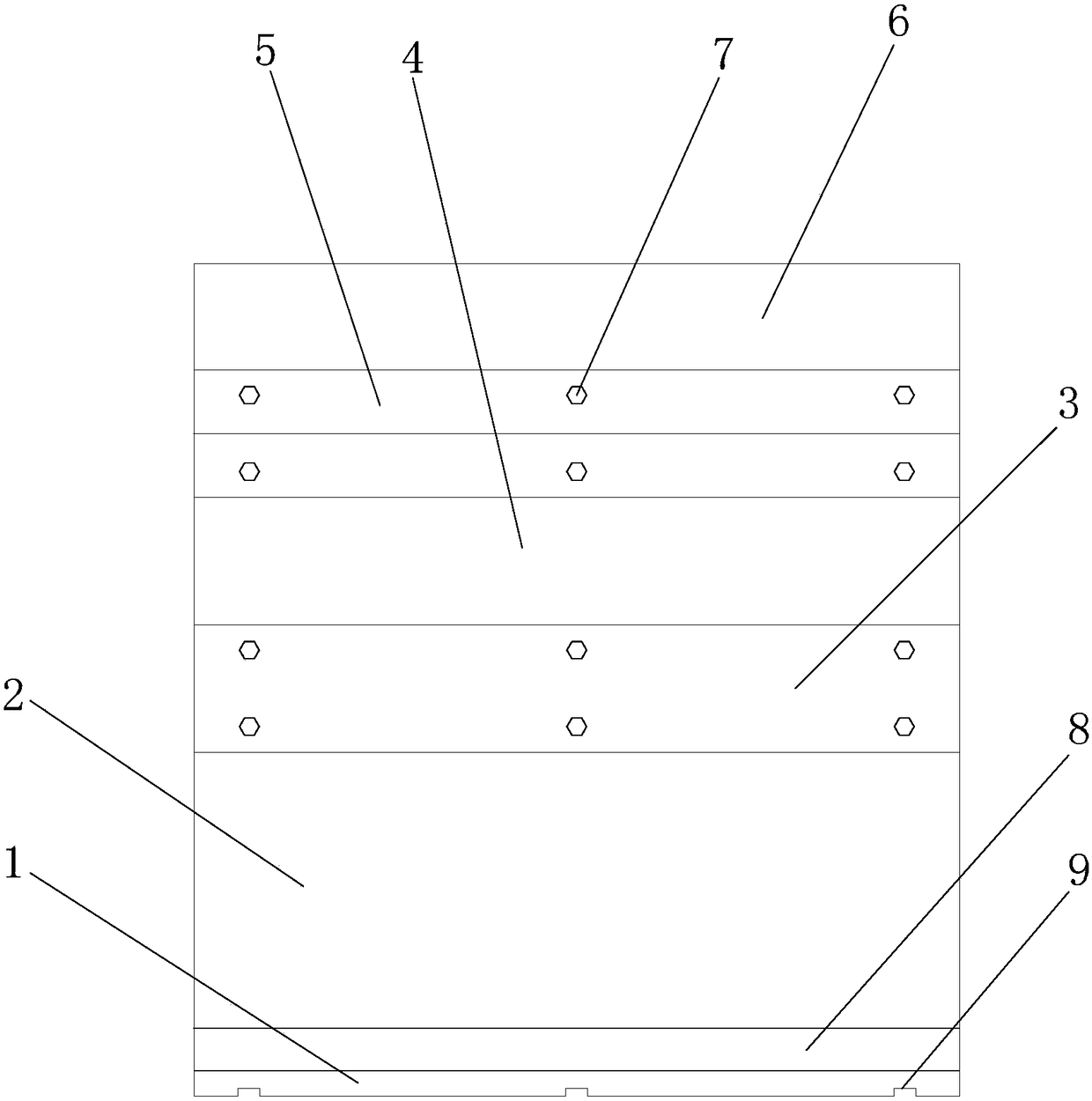
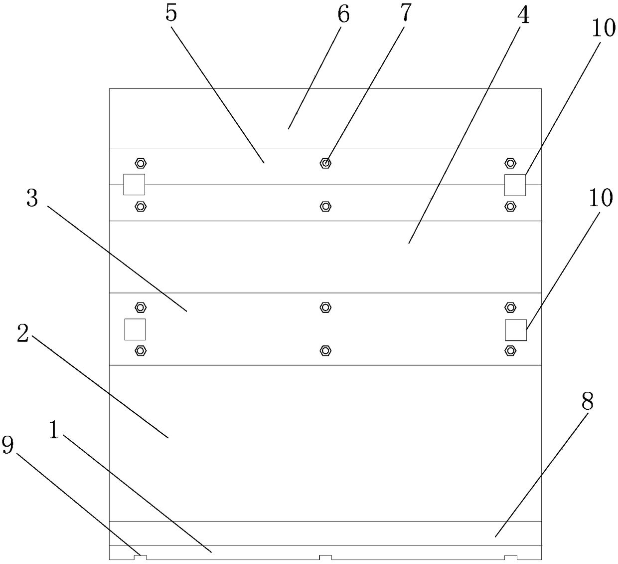
[0016] Such as Figure 1-5 As shown, the road sound insulation board provided by the present invention includes: a strip base plate 1, a vertical base plate 2, a vertical joint plate 3, a vertical extension plate 4, an inclined joint plate 5, an inclined extension plate 6 and mounting bolts 7; The vertical base plate 2 is vertically installed on the strip base plate 1; the upper and lower sides of the vertical joint plate 3 and the upper and lower sides of the inclined joint plate 5 are provided with assembly slots 12; the upper edge of the vertical base plate 2 is inserted In the assembly slot 12 on the lower side of the vertical joint plate 3, the lower edge of the vertical extension plate 4 is inserted into the assembly slot 12 on the upper side of the vertical joint plate 3, and the upper edge of the vertical extension plate 4 is inserted In the assembly slot 12 on the lower side of the inclined joint plate 5, the lower edge of the inclined extension plate 6 is inserted in...
PUM
 Abstract
Description
Claims
Application Information