Curtain wall connecting structure

A technology for connecting structures and curtain walls, which is applied in the direction of walls, building components, building structures, etc., can solve the problems that affect the reuse of aluminum veneers and aluminum profiles, the flexibility is not high, and the operation is complicated, so as to achieve many changes in appearance and convenience Operating procedures, the effect of not easy to fall off

Pending Publication Date: 2018-06-29
浙江德清森朗装饰材料有限公司
View PDF0 Cites 4 Cited by
  • Summary
  • Abstract
  • Description
  • Claims
  • Application Information

AI Technical Summary

Problems solved by technology

Aluminum curtain walls are generally spliced ​​by aluminum veneers and aluminum profiles of various shapes and sizes. The existing aluminum curtain wall nodes are generally screwed or welded, which has

Method used


Image

  • Curtain wall connecting structure
  • Curtain wall connecting structure
  • Curtain wall connecting structure

Examples


Example Embodiment

[0023] Example 1

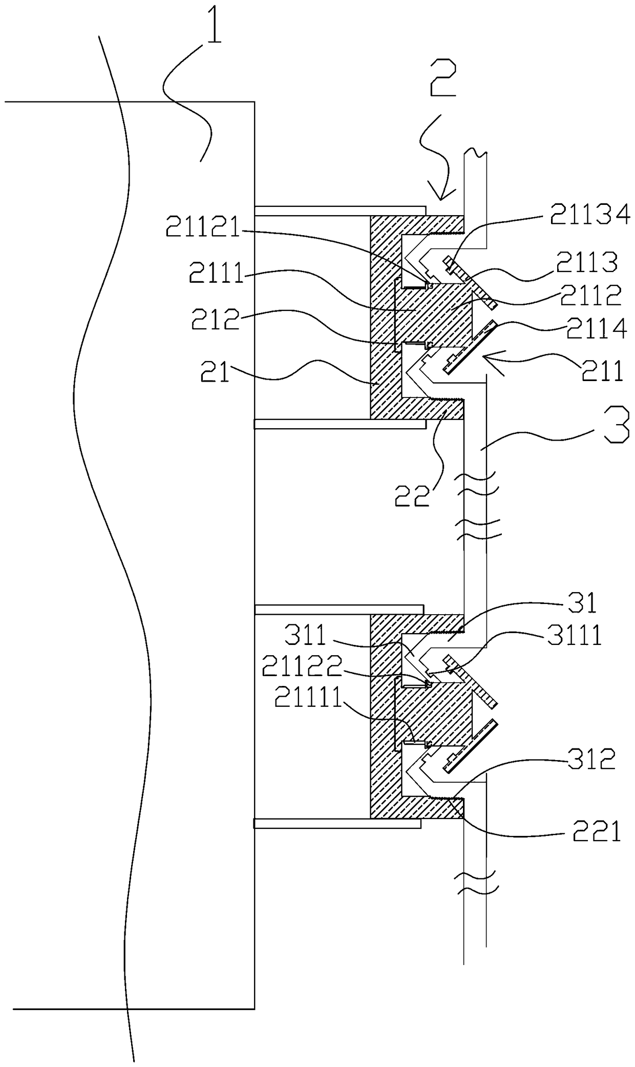
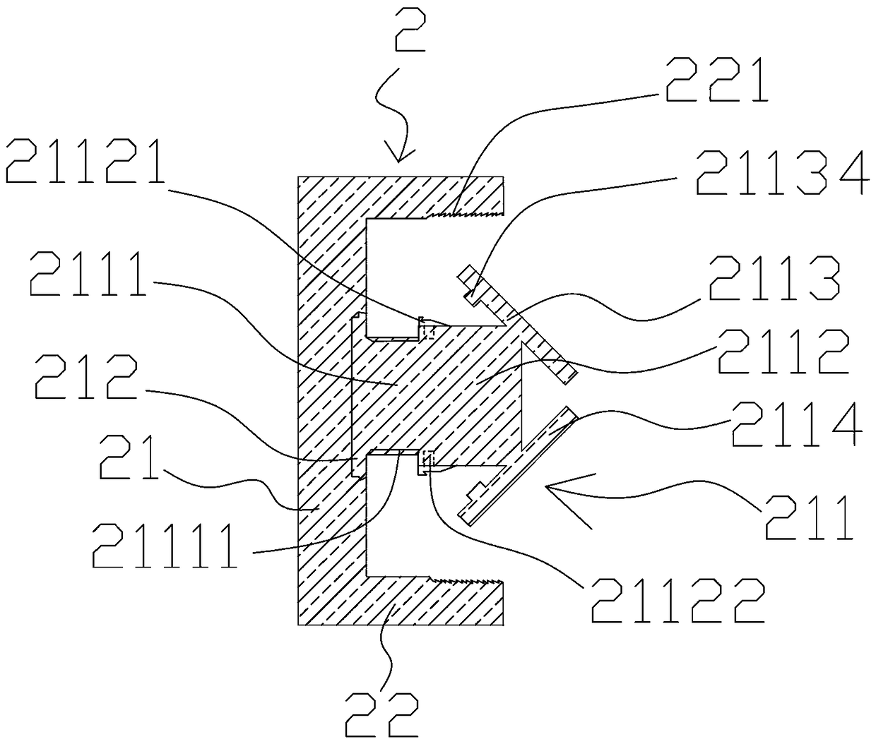
[0024] Such as figure 1 , figure 2 As shown, the curtain wall connection structure provided by this embodiment includes a wall 1, a keel 2 and an aluminum veneer 3. The keel 2 is connected to the wall 1 and the aluminum veneer 3 through different connection structures. Connected, the keel 2 includes a bottom plate 21 and side plates 22 arranged on both sides of the bottom plate 21, the bottom plate 21 is provided with a locking device 211, and the aluminum veneer 3 is engaged with the locking device 211 The locking device 211 includes a fixed base 2111 connected to the bottom plate 21, a telescopic head 2112 sleeved with the fixed base 2111, and an upper locking member 2113 and an upper locking member 2113 that are arranged obliquely and symmetrically to the telescopic head 2112. The lower locking part 2114, the telescopic range of the telescopic head 2112 can be set according to different installation requirements, for example, when the telescopic head 2112 i...

Example Embodiment

[0033] Example 2

[0034] The difference between this embodiment and the first embodiment is that the locking devices 211 are distributed on the bottom plate 21 at intervals. It can save a large part of the material and reduce the cost; in general, only need to lock the two ends of the flange 31 of the aluminum veneer 3 to stabilize the aluminum veneer 3, so the locking devices 211 are distributed at intervals. Determined by the length of the aluminum veneer 3.

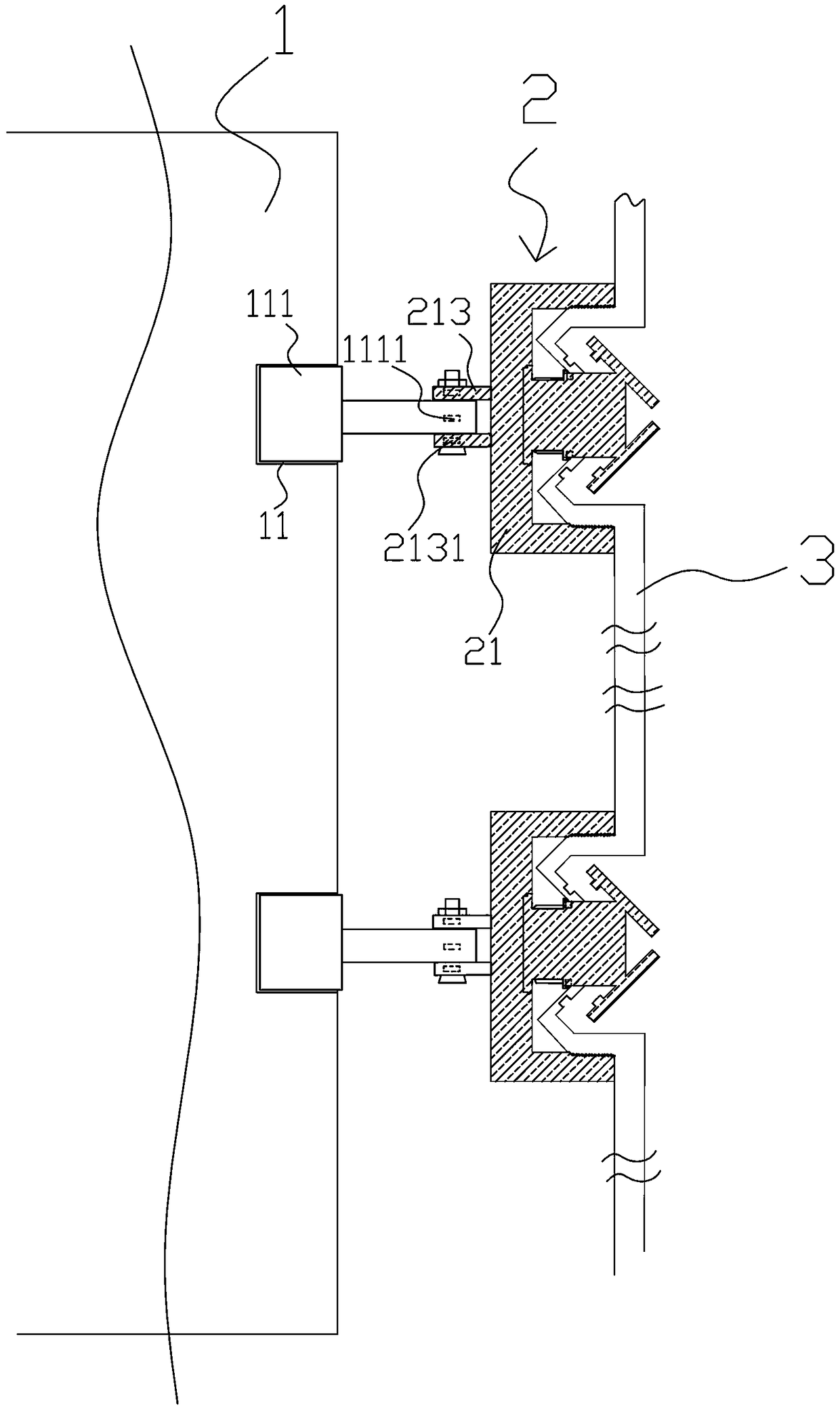
[0035] Such as image 3 As shown, the wall 1 is provided with a recessed installation groove 11, and a telescopic device 111 is provided in the recessed installation groove 11, and the telescopic end of the telescopic device 111 is connected with the keel 2. The telescopic device 111 is a telescopic cylinder, and its telescopic and telescopic length can be controlled by electrification.

[0036] The telescopic end of the telescopic device 111 is provided with a screw hole 1111 arranged perpendicular to the telescopic dire...


PUM


Abstract

The invention discloses a curtain wall connecting structure comprising a wall body, a keel and an aluminum veneer. The keel comprises a bottom plate and side plates arranged on the two sides of the bottom plate, a locking device is arranged on the bottom plate, and the aluminum veneer and the locking device are connected in a clamped mode. The locking device comprises a fixed base and a telescopichead connected with the fixed base in a sleeving mode and further comprises an upper locking piece and a lower locking piece which are mutually obliquely and symmetrically arranged on the telescopichead. A flanging is arranged on the aluminum veneer, a barb is arranged on the flanging, the flanging is placed in a gap formed by the side plates and the locking device, so that the barb abuts against the upper locking piece or the lower locking piece, and thus clamped connection of the aluminum veneer and the locking device is achieved. According to the curtain wall connecting structure, weldingis not needed, mounting and dismounting are convenient, damage to the structure in mounting and dismounting is small, operation is flexible, easy and convenient, the mounting structure is compact, the firmness is high, and the stability is high.

Description

technical field [0001] The invention relates to the field of building curtain walls, in particular to a curtain wall connection structure. Background technique [0002] The curtain wall is the outer wall enclosure of the building. It is not load-bearing and hangs up like a curtain, so it is also called a hanging wall. It is a light-weight wall with decorative effects commonly used in modern large-scale and high-rise buildings. It usually consists of a panel and a supporting structure behind it. As the competition in the building curtain wall industry continues to intensify, large-scale building curtain wall companies have increasingly frequent mergers and acquisitions and capital operations, domestic excellent building curtain wall manufacturers are paying more and more attention to the research of the industry market, especially the enterprise development environment and customer demand trends An in-depth study of changes. [0003] In recent years, metal curtain walls hav...

Claims


Application Information

Patent Timeline
IPC IPC(8): E04B2/96
CPCE04B2/96
Inventor 阮兴良叶建飞寿敏琪阮兴红韩水凤王菊花
Owner 浙江德清森朗装饰材料有限公司
Why Eureka
Try Eureka