Quickly locked opening shrinking patterned sleeve of porous special-shaped mold core and application method thereof

An anisotropic core technology, applied in the direction of connecting components, pins, mechanical equipment, etc., can solve the problems of unsatisfactory positioning effect of porous anisotropic cores, difficult parts production, and high implementation costs, so as to simplify mold development costs and improve production. Efficiency, the effect of reducing the difficulty of production

Pending Publication Date: 2018-06-29
李旭丹
0 Cites 2 Cited by

AI-Extracted Technical Summary

Problems solved by technology

[0002] The positioning effect of the current porous heterogeneous core is not ideal, the production of parts is difficult, the implementation cost is high, the wel...

Method used

[0037] The other end of the barrel-shaped structure is a plug end, and at least one through hole is provided on the end face of the pl...

Abstract

The invention relates to a quickly locked opening shrinking patterned sleeve of a porous special-shaped mold core. The patterned sleeve is a structure which is used for sleeving and locking a porous special-shaped mold core positioning column (1). An inlet end (4) where the positioning column (1) stretches is left in the patterned sleeve. At least two openings (2) are formed in the inlet end (4) where the positioning column (1) stretches, so that a holding claw (3) which shrinks inward and holds the porous special-shaped mold core positioning column (1) during use is formed on the side wall, corresponding to the inlet end (4), of the patterned sleeve. The difference is that positioning and locking of all freedom degrees are finished by hammering at one time. An expansion bolt overturns externally while the quickly locked opening shrinking patterned sleeve overturns internally.

Application Domain

Dowels

Technology Topic

Biomedical engineering

Image

  • Quickly locked opening shrinking patterned sleeve of porous special-shaped mold core and application method thereof
  • Quickly locked opening shrinking patterned sleeve of porous special-shaped mold core and application method thereof
  • Quickly locked opening shrinking patterned sleeve of porous special-shaped mold core and application method thereof

Examples

  • Experimental program(1)

Example Embodiment

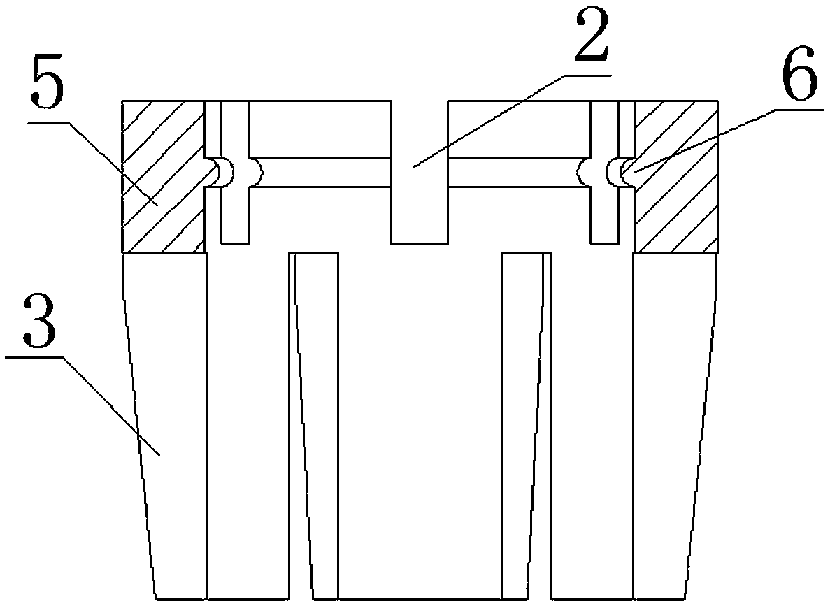
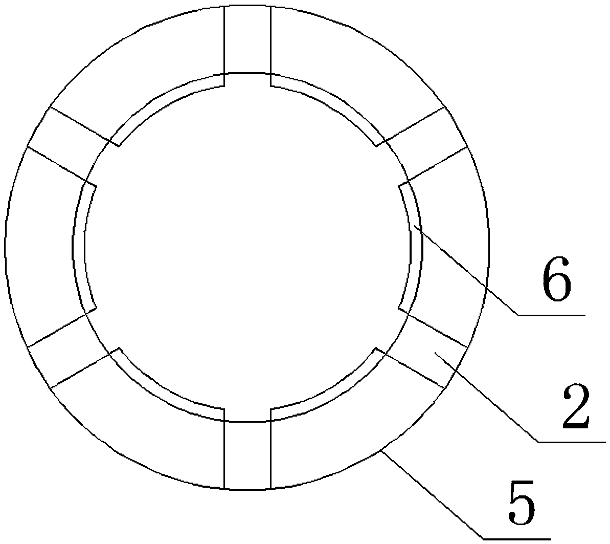
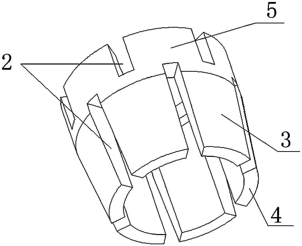
[0034] The present invention proposes a quick-locking opening shrinking flower sleeve with a porous anisotropic core, which is characterized in that: the flower sleeve is a structure that covers and locks the porous anisotropic core positioning column 1 during use, and the flower sleeve has one The entrance end 4 into which the positioning column 1 extends is provided with at least two notches 2 at the entrance end 4 into which the positioning column 1 extends, so that the flower sleeve shrinks inward and hugs it tightly when used to form the side wall of the entrance end 4 The holding claw 3 of the porous heterogeneous core positioning column 1.
[0035] The flower sleeve is a barrel structure with one end open or a tubular structure with two ends open.
[0036] When the flower sleeve is a barrel-shaped structure with an open end, the open end of the barrel-shaped structure is an inlet end, and a holding claw 3 is formed on the side wall of the inlet end.
[0037] The other end of the barrel-shaped structure is a plug end, and at least one through hole is provided on the end surface of the plug end. (When it is convenient to use, nail the flower sleeve into the positioning hole, which also saves costs!)
[0038] When the flower sleeve has a tubular structure with open ends, one end of the flower sleeve for the positioning column 1 is the entrance end 4, and a holding claw 3 is formed at the entrance end.
[0039] The other end of the tubular structure is also provided with a notch 2 so that the end forms a stop claw 5.
[0040] The backstop pawl 5 is provided with a backstop 6 on the inner wall, and an annular groove 7 is provided around the outer wall of the porous anisotropic core positioning column 1. The axial direction of the annular groove is the same as the axial direction of the porous anisotropic core positioning column 1. The stopper 6 is locked into the slot 7 of the positioning column 1 when in use. The position of the annular groove 7 is closer to the larger diameter of the positioning pillar 1 of the circular truncated cone structure.
[0041] The annular clamping groove is coaxial with the porous anisotropic core positioning column 1.
[0042] The radial cross section of the barrel structure or the tubular structure is circular or polygonal.
[0043] Positioning column 1 has a circular truncated cone structure. The position where positioning column 1 connects with porous anisotropic core 9 has the smallest diameter. The inner wall of bottom plate positioning hole 8 is a slope that is compatible with the outer wall of positioning column 1, between the outer wall of positioning column 1 and bottom plate positioning hole 8. A gap is provided for the holding claw 3 to be inserted. When in use, the holding claw 3 moves in the gap and grips the positioning post 1 inwardly along the inner wall of the bottom plate positioning hole 8 to complete positioning.
[0044] The outer wall of the holding claw 3 of the barrel-shaped structure or the tubular structure is a slope structure that gradually shrinks toward the inlet end 4.
[0045] When in use, the positioning column 1 is set into a truncated cone structure, so that the diameter of the position where the positioning column 1 is connected to the porous anisotropic core is the smallest, the side wall of the positioning hole 8 of the bottom plate is set to a slope that is compatible with the outer wall of the positioning column 1, and then the positioning column 1 Insert the smallest diameter end of the bottom plate positioning hole 8, and then nail the flower sleeve into the gap between the outer wall of the positioning column 1 and the bottom plate positioning hole 8 from the other end of the bottom plate positioning hole 8, (such as Figure 4 with 9 The direction of the arrow shown! ) During the falling process of the flower sleeve, under the guiding action of the inclined surface of the positioning hole 8 of the bottom plate, the holding claw 3 gradually tightens inward and holds the positioning post 1 to achieve positioning.
[0046] At the same time, if the flower sleeve has a retreat part 6, during the falling process of the flower sleeve, the retreat pawl 5 also shrinks inward so that the retreat part 6 is gradually locked into the annular groove 7 to prevent retreat.

PUM

no PUM

Description & Claims & Application Information

We can also present the details of the Description, Claims and Application information to help users get a comprehensive understanding of the technical details of the patent, such as background art, summary of invention, brief description of drawings, description of embodiments, and other original content. On the other hand, users can also determine the specific scope of protection of the technology through the list of claims; as well as understand the changes in the life cycle of the technology with the presentation of the patent timeline. Login to view more.

Similar technology patents

Graphene film and preparation method therefor

Owner:CHANGZHOU FUXI TECH CO LTD

Driving working load calculation method of automobile driver

InactiveCN101690666AImprove accuracy and timelinessEasy to operate
Owner:BEIJING UNIV OF TECH

Classification and recommendation of technical efficacy words

  • Reduce production difficulty
  • easy to operate

Double-sided display panel and double-sided display device

ActiveCN103257474AReduce the difficulty of the preparation processReduce production difficulty
Owner:BOE TECH GRP CO LTD

Non-vacuum continuous production equipment and process of copper chromium zirconium alloy

InactiveCN103302263AReduce production difficultyRealize continuous production
Owner:JIANGSU KINDLE COPPER

Twisted optical fiber and manufacturing method thereof

ActiveCN105242348AThe preparation method is simple and reliableReduce production difficulty
Owner:YANGTZE OPTICAL FIBRE AND CABLE JOINT STOCK LIMITED COMPANY

Reinforcement sleeve grouting connecting process suitable for fabricated building

InactiveCN111636625AReduce production difficultylow cost
Owner:中建六局(天津)绿色建筑科技有限公司

Manufacturing method of twisted optical fiber

ActiveCN103359929AReduce production difficultylow equipment requirements
Owner:上海康阔光智能技术有限公司

Lancet device

InactiveUS7303573B2inexpensively mass-producedeasy to operate
Owner:ABBOTT DIABETES CARE INC

Rapid and non-invasive optical detection of internal bleeding

InactiveUS20050065436A1easy to operaterapid and accurate result
Owner:HO WINSTON ZONH +2
Why Eureka
Try Eureka