Shifting roll and shifting method

A technology for shifting clutches and gears, applied in the direction of components with teeth, belts/chains/gears, mechanical equipment, etc., can solve the problems of increased burden and time-consuming synchronization, improve operational reliability and achieve cost efficiency , the effect of high operational reliability

Active Publication Date: 2018-06-29
GETRAG GETRIEBE & ZAHNRADFABRIK HERMANN HAGENMEYER GMBH & CO KG
View PDF9 Cites 0 Cited by
  • Summary
  • Abstract
  • Description
  • Claims
  • Application Information

AI Technical Summary

Problems solved by technology

This is time-consuming on the one hand and additionally burdens the corresponding synchronization

Method used


Image

  • Shifting roll and shifting method
  • Shifting roll and shifting method
  • Shifting roll and shifting method

Examples


Embodiment Construction

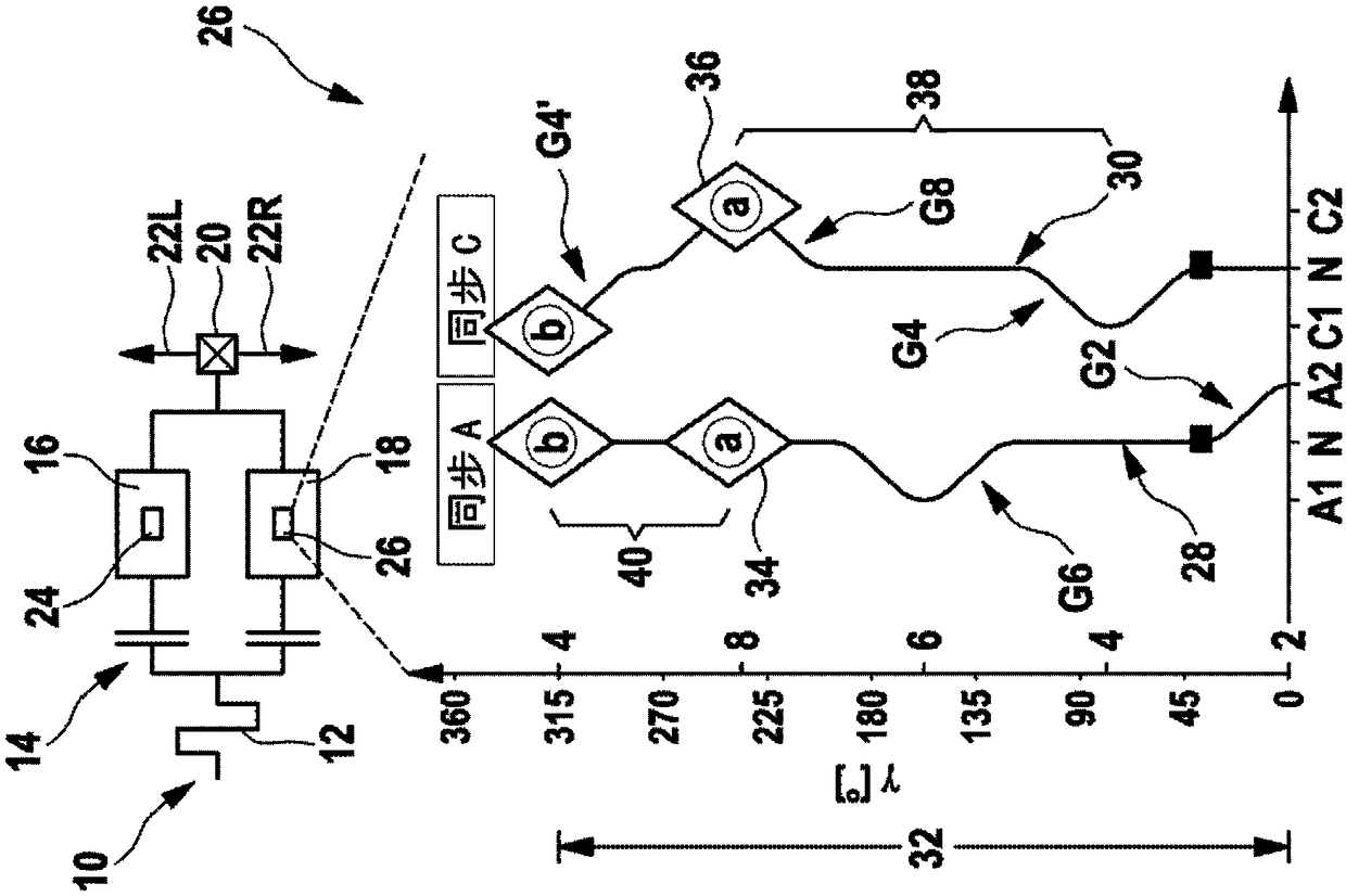
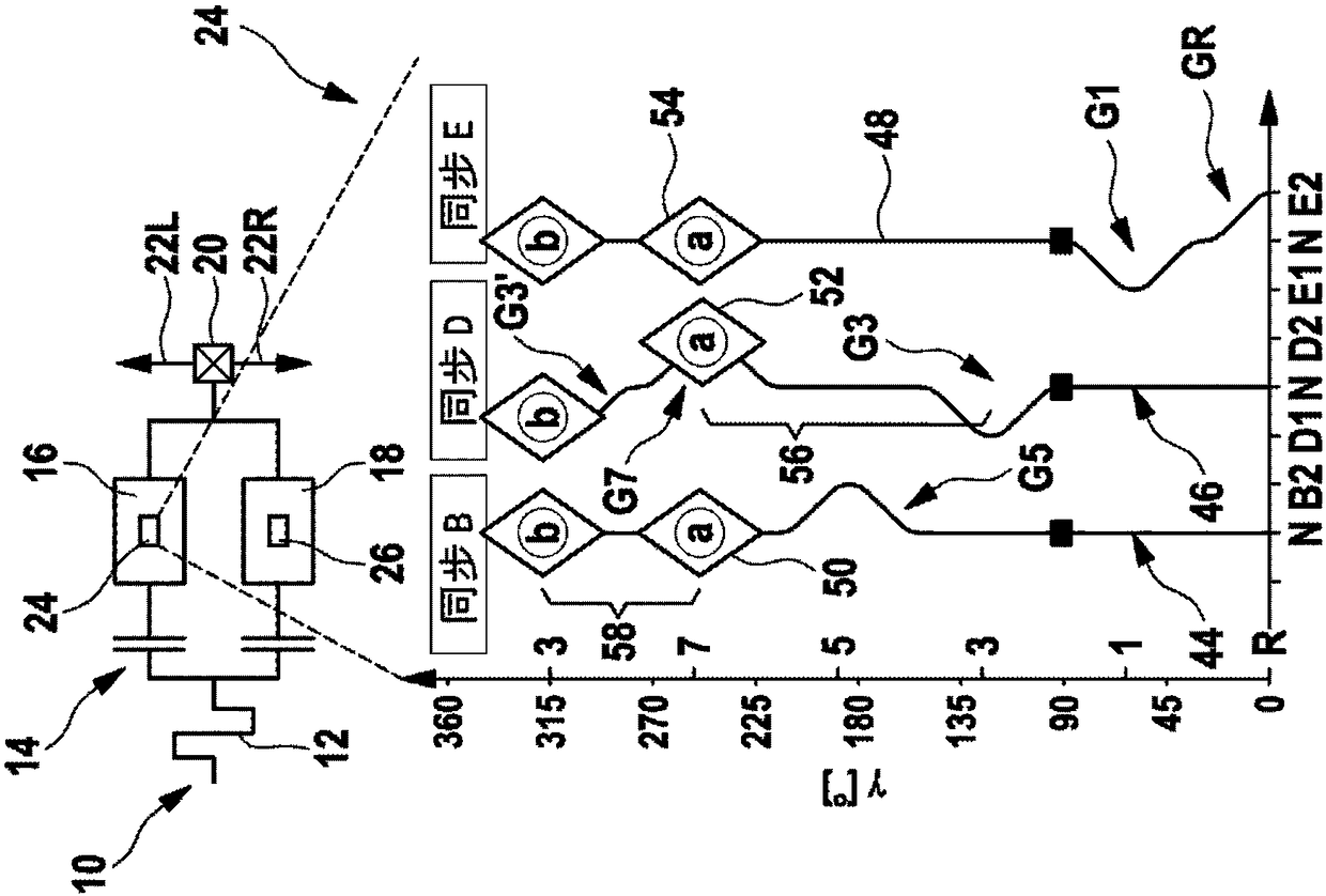
[0080] figure 1 A drive line 10 for a motor vehicle, in particular a passenger car, is shown schematically.

[0081] The drive line 10 has a drive motor 12 which can be formed, for example, as an internal combustion engine motor or as a hybrid drive. Furthermore, the drive line 10 contains a clutch configuration, which is here formed as a double clutch configuration 14 . The drive line 10 also has a countershaft transmission in the form of a spur gear, which has a plurality of forward gears and usually at least one reverse gear. Here, the transmission is divided into a first subtransmission 16 and a second subtransmission 18 , wherein the first subtransmission 16 corresponds to the odd forward gears and reverse gear, and wherein the second subtransmission 18 corresponds to the even forward gears.

[0082] The subtransmissions 16 , 18 are each connected to the drive motor 12 via a clutch of the dual clutch arrangement 14 . The outputs of the subtransmissions 16 , 18 are conn...


PUM


Abstract

Provided is a shifting roll used for an automatic transmission of a vehicle. The shifting roll has a shifting roll body rotating around the axis of a rotary shaft. At least one first shifting profileis formed on the shifting roll body. The first shifting profile extends on a circumferential section of the shifting roll body and a first synchronizing part can be joined on the first shifting profile. The first synchronizing part is folded correspondingly to a first shifting clutch of the transmission of the vehicle, wherein the first shifting profile has a first gear section and a second gear section. The first gear section corresponds to the position of the first shifting clutch folded by the first shifting clutch. The second gear section is spaced from the first gear section at the interval of a first circumference distance and corresponds to the position of a second shifting clutch folded by the first shifting clutch. The first shifting profile has a third gear section. The third gear section corresponds to the position of the first shifting clutch folded by the first shifting clutch and enables the second gear section to be arranged between the first gear section and the third gear section in the arrangement manner in the peripheral direction.

Description

technical field [0001] The invention relates to a shifting roller for an automatic transmission of a vehicle, which has a shifting roller body rotatable about an axis of rotation, on which shifting roller body at least one first shifting profile is formed, the first shifting The gear profile surface extends over a circumferential section of the shift roller body and can engage thereon a first synchronizing element corresponding to a first gear clutch plate pack of a vehicle transmission, wherein the first gear shift profile The face has a first gear section corresponding to the first shift clutch position of the first shift clutch plate stack and a second gear section corresponding to the first The gear segments are spaced apart by a first circumferential spacing and correspond to a second shift clutch position of the first shift clutch plate pack. [0002] Furthermore, the present invention relates to a method for carrying out at least one shift in a vehicle transmission hav...

Claims


Application Information

Patent Timeline
Patent Type & Authority Applications(China)
IPC IPC(8): F16H63/16F16H61/688
CPCF16H61/688F16H63/16F16H63/18
Inventor 斯特凡·卡普马丁·沙勒尤莉亚·盖格
Owner GETRAG GETRIEBE & ZAHNRADFABRIK HERMANN HAGENMEYER GMBH & CO KG
Why Eureka
Try Eureka