Self-installed camera

A camera and self-installation technology, applied in image communication, TV, color TV, etc., can solve the problems of reducing work efficiency, dust ingress, camera damage, etc., and achieve the effect of reducing work steps, improving work efficiency, and reducing filling work

Active Publication Date: 2018-06-29
深圳市兆能讯通科技有限公司
View PDF6 Cites 2 Cited by
  • Summary
  • Abstract
  • Description
  • Claims
  • Application Information

AI Technical Summary

Problems solved by technology

[0004] (1) For the installation of the camera, in order to install the camera stably, it is necessary to drill holes in the wall before fixing the camera. However, other drilling tools are required for drilling, which will inevitably affect the installation efficiency of the camera. , thereby reducing work efficiency
[0005] (2) A large amount of dust will be generated during the drilling process. The large amount of wall dust generated by the camera installed during the drilling process has not been processed, and a large amount of dust will enter the air. On the one hand, it will pollute the environment. Will affect the operation of drilling personnel
[0006] (3) After the drilling is completed, fix the camera. Usually, a large number of bolts or screws are used to fix the camera. Generally, bolts or screws are used to fix the camera into the wall to fix the camera. Misoperation will inevitably cause damage to the camera. , Bolts or screws are driven into the wall again, which will inevitably increase the damage area of ​​the wall

Method used


Image

  • Self-installed camera
  • Self-installed camera
  • Self-installed camera

Examples


Embodiment 1

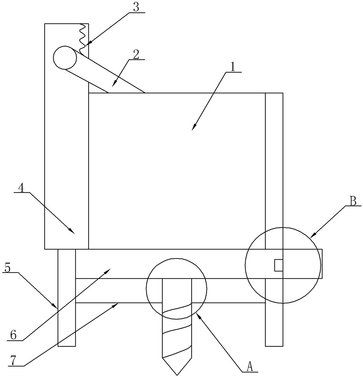
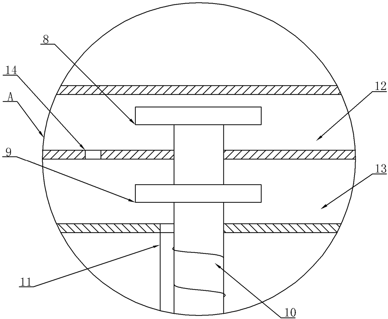
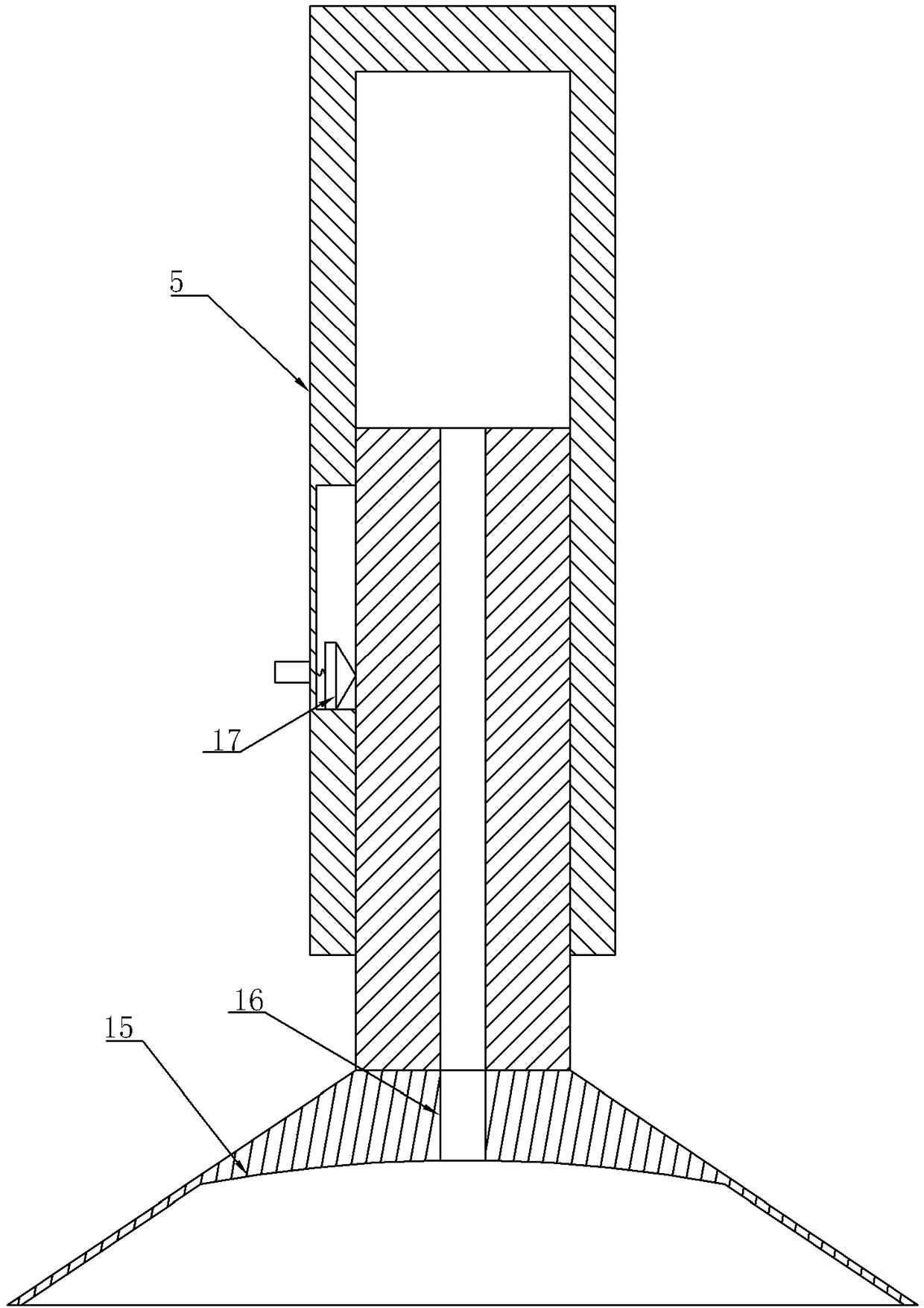
[0027] As attached figure 1 , Attached figure 2 , Attached image 3 And Figure 4 As shown, a self-installing camera includes a camera 1, a high-pressure air box 4 and a support frame 19. The high-pressure air box 4 is mounted on the support frame 19 and is detachably connected to the support frame 19. The camera 1 is fixed on the support frame 19 by fastening bolts. The high-pressure air box 4 is provided with a spring 3 and a compression rod 2. The compression rod 2 is hinged with the high-pressure air box 4, and one end of the spring 3 is fixed on the high-pressure air box 4. The other end of the spring 3 is fixed on the compression rod 2. The spring 3 pushes the compression rod 2 to rotate on the high-pressure air box 4. The compression rod 2 can further compress the camera 1 on the support frame 19 under the squeeze action of the spring 3 on. Both sides of the support frame 19 are fixed with a fixed rod 5, the fixed rod 5 includes an inner rod and an outer rod sleeved on...


PUM


Abstract

The invention relates to the technical field of automation of a building, and discloses a self-installed camera. The self-installed camera comprises a camera, a high-pressure air tank and a supportingbracket; both sides of the supporting bracket are provided with fixing rod, and the fixing rods comprise inner rods and outer rods sleeved at outsides of the inner rods; the side walls of the outer rods are provided with button switches, lower parts of the inner rods are fixed with suction disks; unidirectional valves are arranged on the suction disks, and a rotating block and a mixing block arearranged between the fixing rods; the rotating block is provided with a rotating cavity connected with the high-pressure air tank, and the mixing block is provided with a mixing cavity; a first electromagnetic valve is arranged on the mixing cavity, and the mixing cavity is provided with a discharge pipe connected with the mixing cavity; the joint of the mixing cavity and the discharge pipe is provided with a diaphragm, a drill bit crossing through the mixing cavity is arranged in a rotating cavity; the drill bit is rotationally connected with the rotating block and the mixing block, the partwhere the drill bit locates at the rotating cavity is provided with a spiral blade, and the part where the drill bit locates at the mixing cavity is provided with a mixing blade. The self-installed camera is simple in structure, convenient to install the camera, and able to reduce workload and improve the camera installing efficiency.

Description

Technical field [0001] The invention relates to the technical field of building automation, in particular to a self-installing camera. Background technique [0002] The camera is a semiconductor imaging device, which has the advantages of high sensitivity, strong light resistance, small distortion, small size, long life and anti-vibration. It is usually used in surveillance camera systems. Especially in the current building automation system, in order to improve safety protection measures, a camera must be installed. The well-known Skynet surveillance system in my country is also a surveillance network composed of a large number of cameras in the streets and alleys. Therefore, cameras have become an indispensable part of our lives. [0003] However, the camera installation has the following problems: [0004] (1) The installation of the camera, in order to install the camera stably, it is necessary to drill the wall before fixing the camera. However, drilling requires the use of ot...

Claims


Application Information

Patent Timeline
Patent Type & Authority Applications(China)
IPC IPC(8): F16M11/04F16M13/02H04N5/225B28D1/14
CPCF16M11/04F16M13/02B28D1/14H04N23/50
Inventor 冯仁海
Owner 深圳市兆能讯通科技有限公司
Why Eureka
Try Eureka