
Vehicle lamp figure and production method thereof

A pattern and lighting technology, applied in the direction of headlights, road vehicles, vehicle parts, etc., can solve problems such as monotony and rigidity, and achieve the effect of strong graininess, beautifying lamps, and ensuring lighting uniformity.

Pending Publication Date: 2018-06-29
HASCO VISION TECHNOLOGY CO LTD
View PDF12 Cites 5 Cited by
  • Summary
  • Abstract
  • Description
  • Claims
  • Application Information

AI Technical Summary

Problems solved by technology

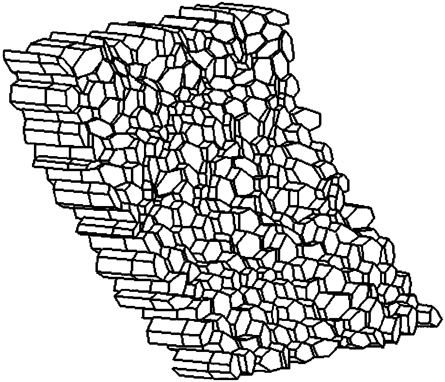
[0005] The purpose of the present invention is to provide a vehicle lamp pattern and its production method to solve the technical problem that the existing regular and uniform pattern division method tends to cause the transmitted luminous effect to be a flat effect, which appears monotonous and dull

Method used


Image

  • Vehicle lamp figure and production method thereof
  • Vehicle lamp figure and production method thereof
  • Vehicle lamp figure and production method thereof

Examples


specific Embodiment 1

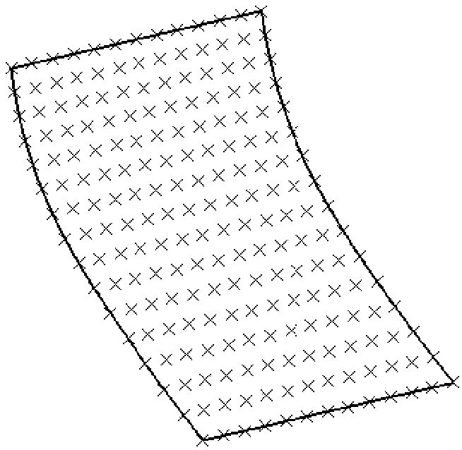
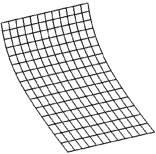
[0064] figure 2 - Figure 11 Shown is the specific implementation steps of generating the light distribution pattern on a custom surface.

[0065] In step a, define the closed area of ​​the surface on which the light distribution pattern of the vehicle light is to be generated, that is, define the boundary of the area where the light distribution pattern of the vehicle light is to be generated.

[0066] Step b, such as figure 2 As shown, discrete points are defined in two directions in the closed area, and the discrete points can be located on the boundary of the closed area. The number of discrete points can be determined as required. The denser the discrete points are, the more polygons will be formed in the light distribution pattern of the car light. Connect two adjacent points sequentially in two directions to form multiple quadrilateral small unit areas, each adjacent two small unit areas share one side, and every four small units share vertices, such as image 3 ...


PUM


Abstract

The invention discloses a vehicle lamp figure and a production method thereof, and relates to the technical field of vehicle lamp lighting. The technical problems that an existing rule is unified, a figure dividing method is easy, and consequently the transmitted glowing effect is the plane effect, and it shows monotonous and stiff are solved. The vehicle lamp figure is composed of a plurality ofpolygons or similar polygons, the single polygons are generalized polygons, peaks of the polygons share a plane or curve face, edges of the similar polygons are curves, and the peaks of the similar polygons share a plane or curve face; and front projections of at least two polygons or similar polygons are not completely the same, and any two adjacent polygons or similar polygons can intersect or be collinear.

Description

technical field [0001] The invention relates to the technical field of vehicle lamp lighting, in particular to a vehicle lamp pattern and a production method thereof. Background technique [0002] At present, in the design of car lights, in order to obtain a uniform lighting effect, regular patterns such as fish eyes or horizontal and vertical stripes are generally added to the reflecting cavity or the light distribution mirror to diffuse the light. [0003] However, the inventors of the present application found that whether using fisheye patterns or designing horizontal or vertical striped patterns, the division patterns of the patterns are relatively regular, and the shape designed on this basis is too simple; moreover, the transmitted luminous effect They are also flat effects, which appear monotonous and dull. [0004] Therefore, how to provide a lamp pattern for vehicles and its production method can change the existing regular and unified pattern division method, so ...

Claims


Application Information

Patent Timeline
Patent Type & Authority Applications(China)
IPC IPC(8): F21S41/20F21S41/37F21S43/20F21S43/33F21W107/10
CPCF21S43/26
Inventor 王华刘西原杨海华何士群
Owner HASCO VISION TECHNOLOGY CO LTD
Learn More