Environmental testing device applied to complex stress condition

An environmental test device, a technology of complex stress, applied in the testing of machine/structural components, measuring devices, vibration testing, etc., can solve problems such as inability to achieve, and achieve the effects of convenient operation, reasonable design and low cost

Active Publication Date: 2018-06-29
NUCLEAR POWER INSTITUTE OF CHINA
View PDF9 Cites 5 Cited by
  • Summary
  • Abstract
  • Description
  • Claims
  • Application Information

AI Technical Summary

Problems solved by technology

[0005] The technical problem to be solved by the present invention is: the experimental device in the prior art cannot simultaneously complete complex stress application tasks such as temperature, humidity, mold, salt spray and other complex environments such as multi-axis multi-degree-of-freedom vibration stress, and the purpose is to provide An environmental test device suitable for complex stress conditions is developed. Through the optimization of the structure, it can effectively achieve the application of harsh stress environments such as temperature, humidity, mold, and salt spray, and at the same time effectively realize the 3-axis and 6-freedom of the test equipment Degree Test Requirements

Method used


Image

  • Environmental testing device applied to complex stress condition
  • Environmental testing device applied to complex stress condition

Examples


Embodiment 1

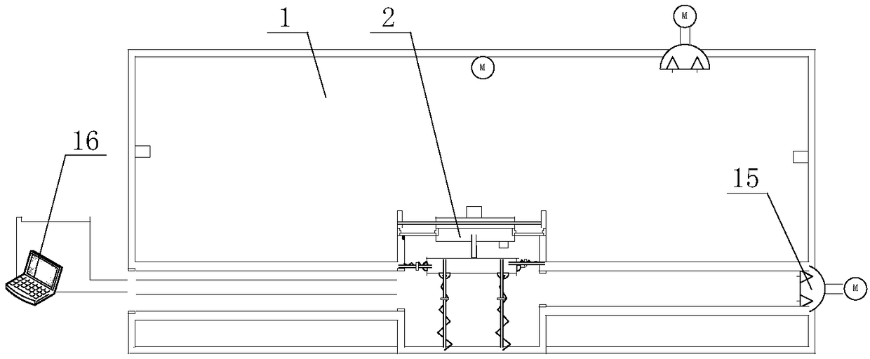
[0029] An environmental test device suitable for complex stress conditions, such as figure 1 As shown, it includes an environment-strengthening box body 1 with a mounting opening, an equipment installation base 2 arranged at the position of the installation opening in the environment-enhancing box body 1, an installation fixture 3 arranged around the installation opening, the inner ring and the equipment installation base The seat 2 is sealed and connected, and the outer ring is sealed and connected with the mounting fixture 3. The elastic sealing ring 4 is provided with a vibration generation system that drives the equipment installation base 2 to vibrate outside the environment-strengthening box 1 .

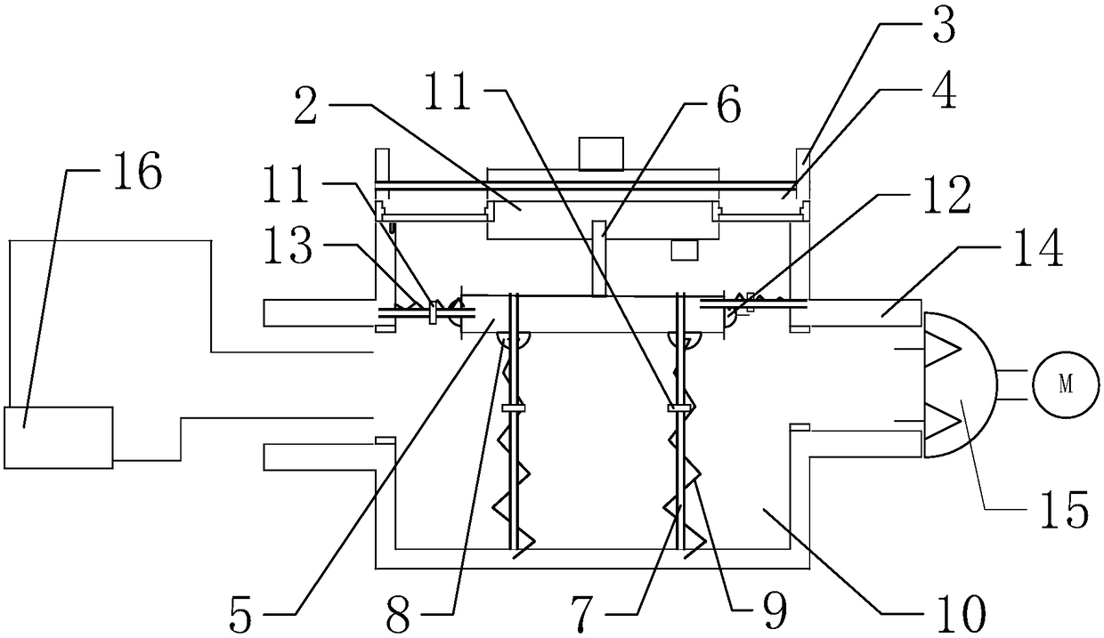
[0030] In this embodiment, the vibration generation system includes a vibration base 5, one end of which is fixed on the vibration base 5, and the other end is fixed on the transmission rod 6 on the equipment installation base 2, which is arranged on the vibration base 5 to driv...

Embodiment 2

[0040] The difference between this embodiment and Embodiment 1 is that this embodiment further optimizes the structure of the vibration generation system, and the specific settings are as follows:

[0041] The outer ring of the elastic sealing ring 4 is sealingly connected with the top end of the mounting fixture 3, and the vibration base 5 is arranged at the bottom position of the mounting fixture 3, such as figure 1 and figure 2 shown. Moreover, in this embodiment, the guide rod 7 and the inner pipe are provided with limit nuts 11, which can effectively avoid damage to the elastic sealing ring 4 due to excessive vibration exceeding the elastic deformation of the elastic sealing ring 4 .

Embodiment 3

[0043] The difference between this embodiment and Embodiment 1 is that a ventilation cooling device 15 is also added in this embodiment, and the specific settings are as follows:

[0044] The insulation box 10 is provided with a heat insulation isolation tube 14 communicating with the interior of the isolation box 10 , and a ventilation cooling device 15 is installed on the insulation box 14 .

[0045] Moreover, the structure of the limiting device in this embodiment is different. In this embodiment, the limiting device includes a spherical groove arranged on the bottom surface of the isolation box 10, and a hinged ball arranged in the spherical groove and hinged to the bottom surface of the isolation box 10 is fixed on the hinge. A horizontal channel on the ball, the pulley slides inside the horizontal channel.


PUM


Abstract

The invention discloses an environmental testing device applied to a complex stress condition, and solves the problems that complex stress application tasks such as complex environments such as temperatures, humidity, mycete, salt mist and the like and multi-axis multi-freedom degree vibration stress and the like cannot be carried out simultaneously by adopting an experimental device in the priorart. The environmental testing device comprises an environmental strengthening box with a mounting hole, an equipment mounting base arranged at a mounting hole position in the environmental strengthening box, a mounting fixing part arranged around one circle of the mounting hole, an elastic sealing ring of which an inner ring is hermetically connected with the equipment mounting base and an outerring is hermetically connected with the mounting fixing part, and a vibration generation system which is arranged on the outer part of the environmental strengthening box and is used for driving the equipment mounting base to be vibrated. The environmental testing device is designed by utilizing thinking design of multi-layered isolation and technical integration, and complex stress application tasks such as temperatures, humidity, mycete, salt mist and multi-axis multi-freedom degree vibration stress can be carried out simultaneously.

Description

technical field [0001] The invention relates to the field of testing devices, in particular to an environmental testing device suitable for complex stress conditions. Background technique [0002] In scientific research and engineering projects, under the action of various environmental stresses, such as temperature, humidity, mold, salt spray and other stress conditions, the research on the operating characteristics of equipment is often an important indicator for testing equipment capabilities. Due to the harsh environment, which does not conform to the working environment of the vibration test bench, the vibration table cannot be placed in the test box for this harsh environment. on the vibration test bench. This structure leads to high manufacturing cost of the equipment, and at the same time, the structural size of the test equipment is limited. This type of equipment can only be used for equipment with a small volume, and during the experiment, the environmental test ...

Claims


Application Information

Patent Timeline
Patent Type & Authority Applications(China)
IPC IPC(8): G01M7/06
CPCG01M7/06
Inventor 张林吴小飞李明刚闫晓聂常华湛力马新光朱志锋马楠
Owner NUCLEAR POWER INSTITUTE OF CHINA
Why Eureka
Try Eureka