Patrol unmanned rotorcraft
A technology of unmanned rotor and unmanned aerial vehicle, which is applied in the field of unmanned aerial vehicles, can solve the problems of manual inspection and detection of electric shock hazards for workers, and achieve the effect of no electric shock hazard and long distance
- Summary
- Abstract
- Description
- Claims
- Application Information
AI Technical Summary
Problems solved by technology
Method used
Image

Examples
Embodiment Construction
[0016] The preferred embodiments of the present invention will be described in detail below in conjunction with the accompanying drawings, so that the advantages and features of the present invention can be more easily understood by those skilled in the art, so as to define the protection scope of the present invention more clearly.
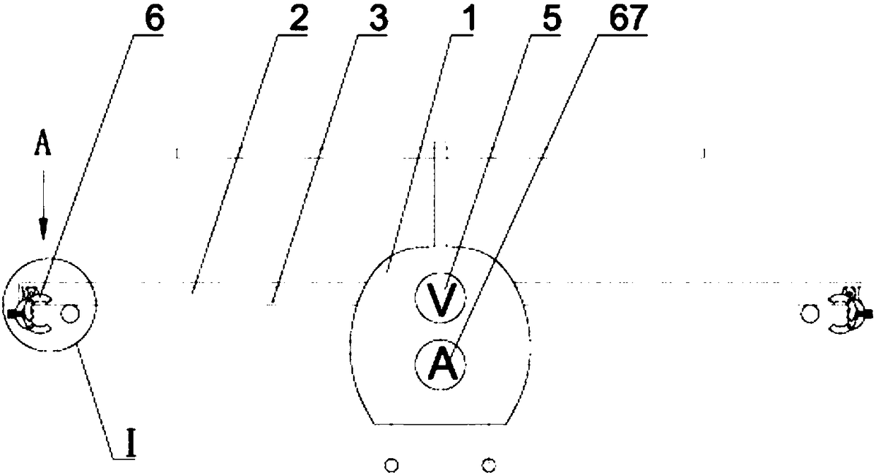
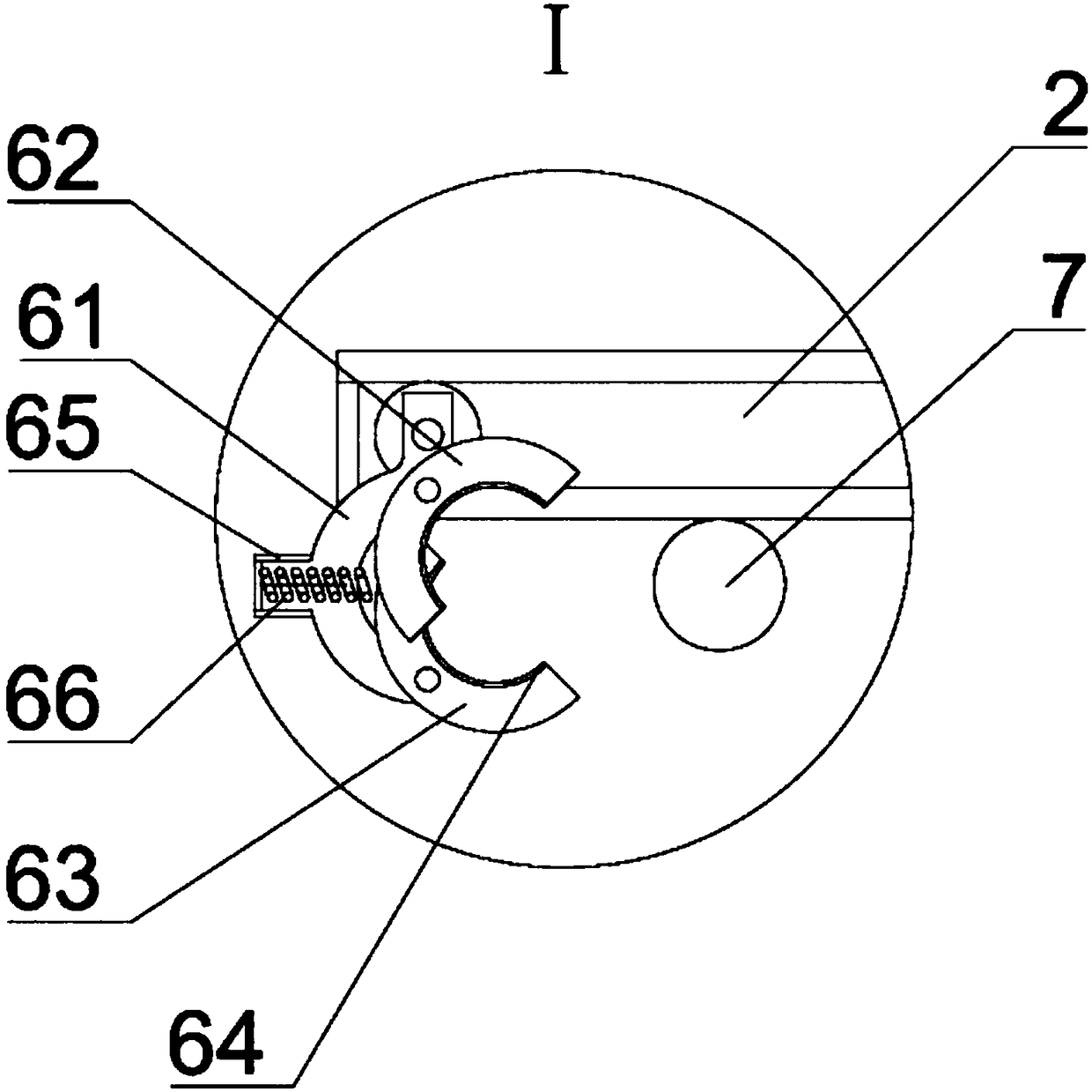
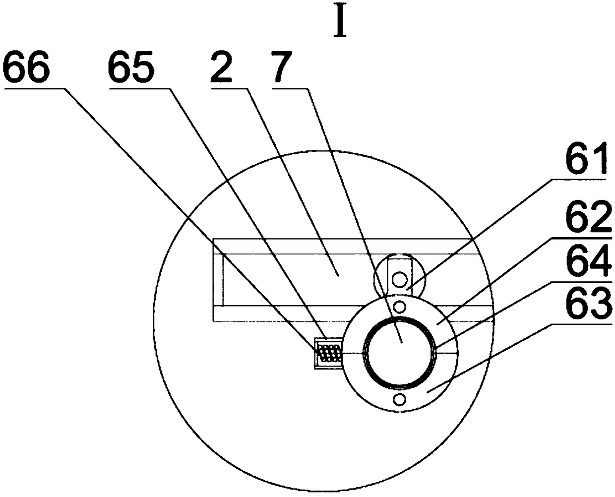
[0017] refer to figure 1 As shown, a kind of inspection rotor UAV of the present invention comprises UAV 1, and a pair of horizontal guide rails 2 are installed symmetrically along the vertical plane in UAV 1, and the material of horizontal guide rail 2 is insulating material, and horizontal guide rail 2 The bottom is connected with conductive stickers 3, and the two conductive stickers 3 are electrically connected with the voltage detection unit 4 in the drone. Each horizontal guide rail 2 is equipped with a running device 5, and each running device 5 is equipped with a Hall sensor assembly6. Since a pair of horizontal guide rails 2 are install...
PUM
 Abstract
Description
Claims
Application Information
 - Generate Ideas
- Intellectual Property
- Life Sciences
- Materials
- Tech Scout
- Unparalleled Data Quality
- Higher Quality Content
- 60% Fewer Hallucinations
Browse by: Latest US Patents, China's latest patents, Technical Efficacy Thesaurus, Application Domain, Technology Topic, Popular Technical Reports.
© 2025 PatSnap. All rights reserved.Legal|Privacy policy|Modern Slavery Act Transparency Statement|Sitemap|About US| Contact US: help@patsnap.com