Phase shifting device, antenna and base station

A phase-shifting and phase-shifter technology, which is applied to antennas, antenna parts, antenna supports/installation devices, etc., can solve the problems of too many cables in phase-shifter components, without reducing the number of cables and solder joints, and achieve improved performance. Effect

Active Publication Date: 2018-06-29
COMBA TELECOM TECH (GUANGZHOU) CO LTD
View PDF8 Cites 5 Cited by
  • Summary
  • Abstract
  • Description
  • Claims
  • Application Information

AI Technical Summary

Problems solved by technology

[0003] In the prior art, it has become a trend to integrate the phase shifter and the combiner module. Usually, the combiner is fixed on the phase shifter, instead of being placed under the vibrator and fixed on the reflector like a conventional antenna. In fact, this solution can produce the phase shifter and combiner as one part, but it does not reduce the number of cables and solder joints, and the phase shifter has too many cables, which is a challenge for phase shifter wiring and welding

Method used


Image

  • Phase shifting device, antenna and base station
  • Phase shifting device, antenna and base station
  • Phase shifting device, antenna and base station

Examples


Embodiment Construction

[0031] The following describes in detail the embodiments of the present invention, examples of which are illustrated in the accompanying drawings, wherein the same or similar reference numerals refer to the same or similar elements or elements having the same or similar functions throughout. The embodiments described below with reference to the accompanying drawings are exemplary and are only used to explain the present invention, but not to be construed as a limitation of the present invention.

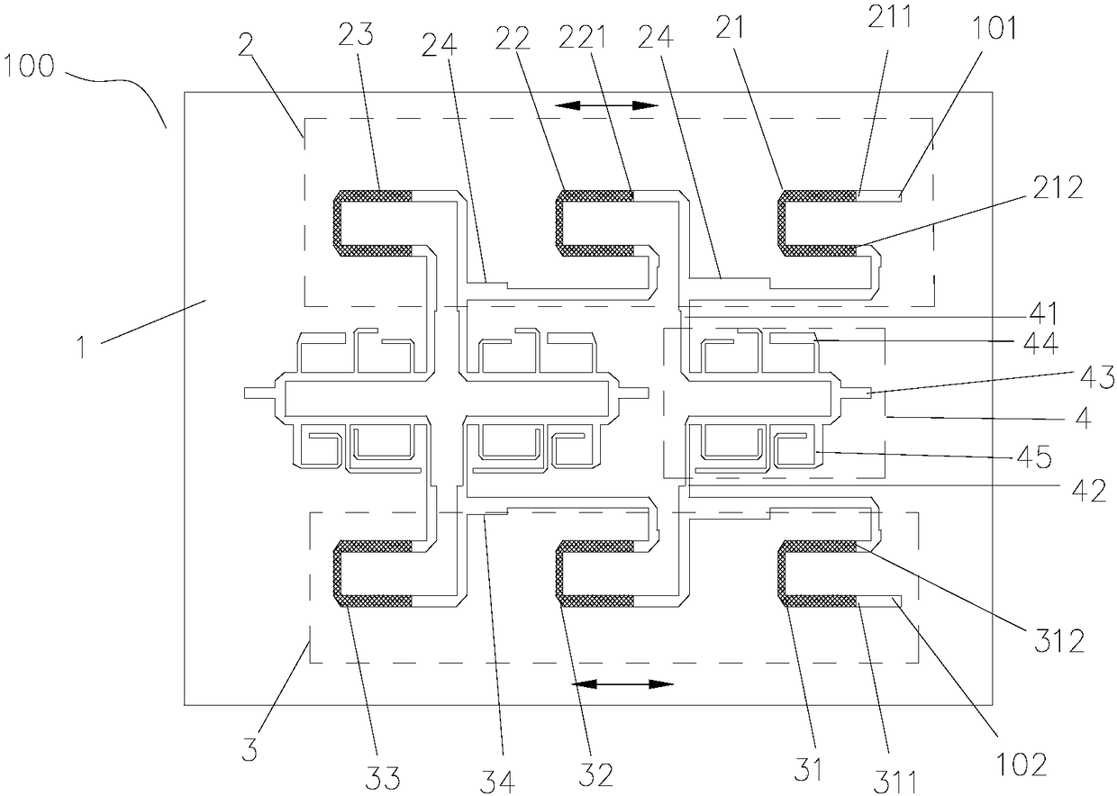
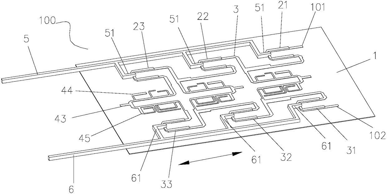
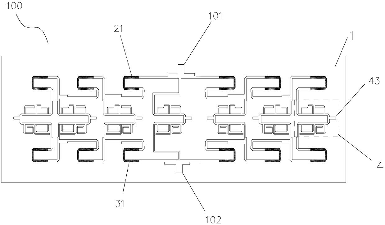
[0032] figure 1 A typical embodiment of the phase shifting device of the present invention is shown. Specifically, the phase shifting device 100 of the present invention includes a first phase shifter 2 , a second phase shifter 3 and at least one combiner 4 , and the combiner 4 is provided in the first phase shifter 2 and the second phase shifter 4 . between the two phase shifters 3. Preferably, the first phase shifter 2 and the second phase shifter 3 are phase shifters of the same...


PUM


Abstract

The invention provides a phase shifting device. The phase shifting device comprises two phase shifters and at least one circuit combiner arranged between the two phase shifters, wherein the circuit combiner comprises an output end and two input ends; each phase shifter comprises at least one output end, one input end of the circuit combiner is connected with the output end of one of the two phaseshifters, and the other input end of the circuit combiner is connected with the output end of the other phase shifter; and each phase shifter comprises at least two U-shaped phase shifting circuits which are sequentially connected, and an output end of each of any two adjacent U-shaped phase shifting circuits is connected with an input end of the other U-shaped phase shifting circuit and the inputend of the circuit combiner, respectively. By utilizing relatively few cables and welding points, the phase shifting device has relatively small volume and relatively high integration level. Correspondingly, the invention further provides an antenna and a base station which adopt the phase shifting device.

Description

technical field [0001] The present invention relates to the field of mobile communication antennas, and in particular, to a phase shifting device, as well as a corresponding antenna and a base station. Background technique [0002] With the development of mobile communications, multi-frequency antennas play an increasingly important role in network coverage. In order to reduce the windward area and facilitate network deployment, the miniaturization of multi-frequency antennas has become a research hotspot for major antenna manufacturers. One solution to the miniaturization of multi-frequency antennas is to use oscillator multiplexing technology, which can replace the traditional two independent arrays with broadband oscillator multiplexing. The phase device is connected to achieve the effect of independent ESC. As the core component of the ESC base station antenna, the performance of the phase shifter directly determines the performance of the ESC antenna, which in turn aff...

Claims


Application Information

Patent Timeline
Patent Type & Authority Applications(China)
IPC IPC(8): H01P1/18H01Q3/32H01Q1/24
CPCH01P1/18H01Q1/246H01Q3/32
Inventor 苏国生
Owner COMBA TELECOM TECH (GUANGZHOU) CO LTD
Why Eureka
Try Eureka