Miniaturized power divider

A power divider and branching technology, which is applied to waveguide devices, circuits, connecting devices, etc., can solve the problems of too many layers of circuit boards, low integration, and large radiation interference, so as to improve transmission capacity and suppress Electromagnetic radiation, strong anti-interference effect

Inactive Publication Date: 2018-06-29
QINGDAO TECHNOLOGICAL UNIVERSITY
View PDF1 Cites 3 Cited by
  • Summary
  • Abstract
  • Description
  • Claims
  • Application Information

AI Technical Summary

Problems solved by technology

Microstrip power splitters are widely used in radio frequency circuits due to their low profile, easy integration, and low cost. However, due to the limitation of 1 / 4 wavelength transmission lines, microstrip power splitters are not easy to achieve miniaturization design
Some of the miniaturized power divider structures based on the serpentine or multi-layer transmission line structure have too many layers of circuit boards, complex structures, and high costs, and some are not highly integrated and are susceptible to environmental interference.
For example, the authorized Chinese invention patent CN201410302256.8 discloses a miniaturized microstrip power splitter, which reduces the volume of the power splitter by arranging the microstrip transmission line in a multi-layer circuit board, but because the three-layer The structure of the circuit board is costly and complex, and all transmission lines are microstrip transmission lines, which generate large radiation interference and are easily interfered by the surrounding environment, which greatly limits the performance of the power splitter
[0006] Today's technology is difficult to simultaneously meet the requirements of low cost, high performance and miniaturization

Method used


Image

  • Miniaturized power divider
  • Miniaturized power divider
  • Miniaturized power divider

Examples


Embodiment 1

[0043] In order to make the object, technical solution and advantages of the present invention clearer, the present invention will be described in further detail below with reference to the accompanying drawings and preferred embodiments. However, it should be noted that many of the details listed in the specification are only for readers to have a thorough understanding of one or more aspects of the present invention, and these aspects of the present invention can be implemented even without these specific details.

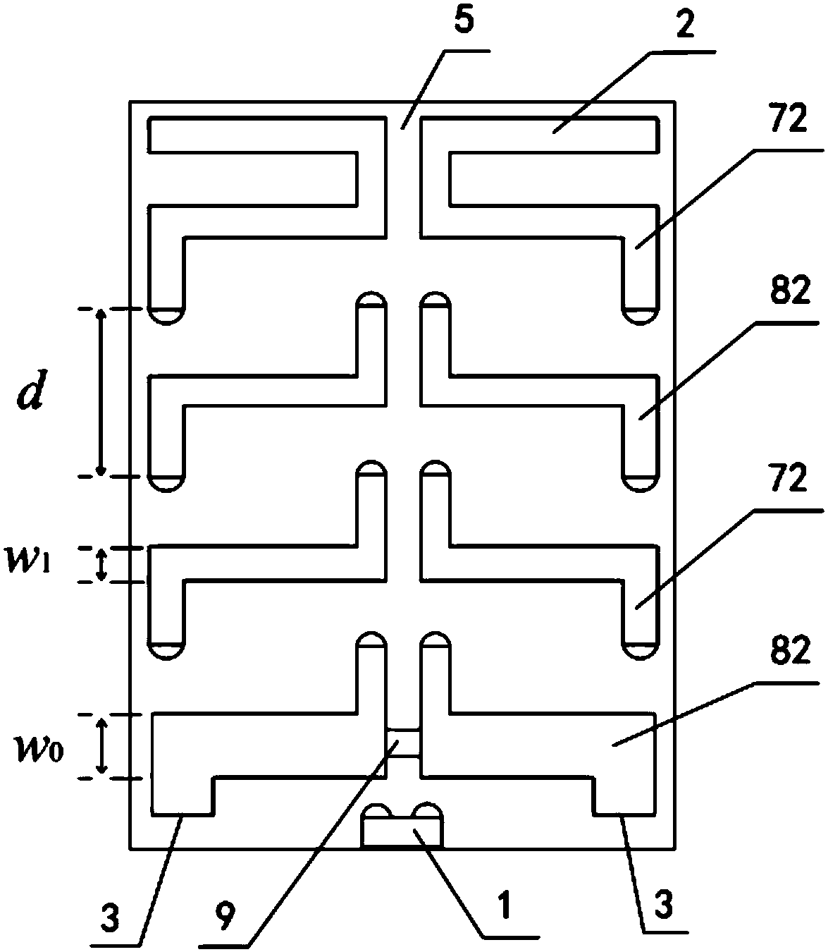
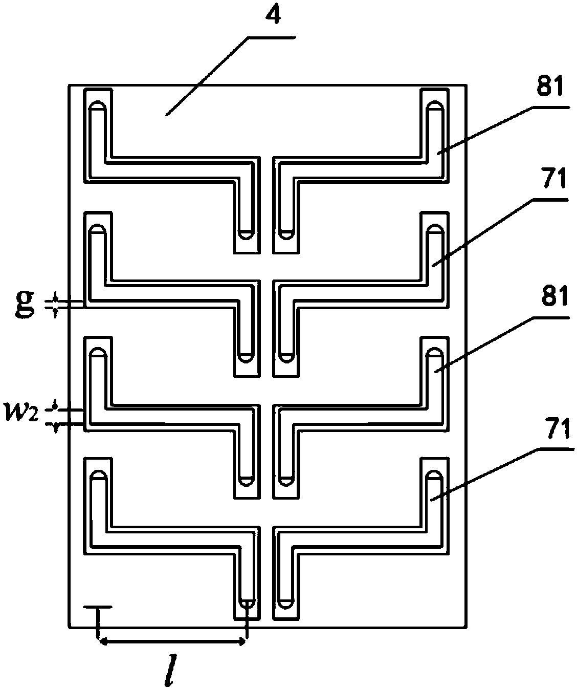
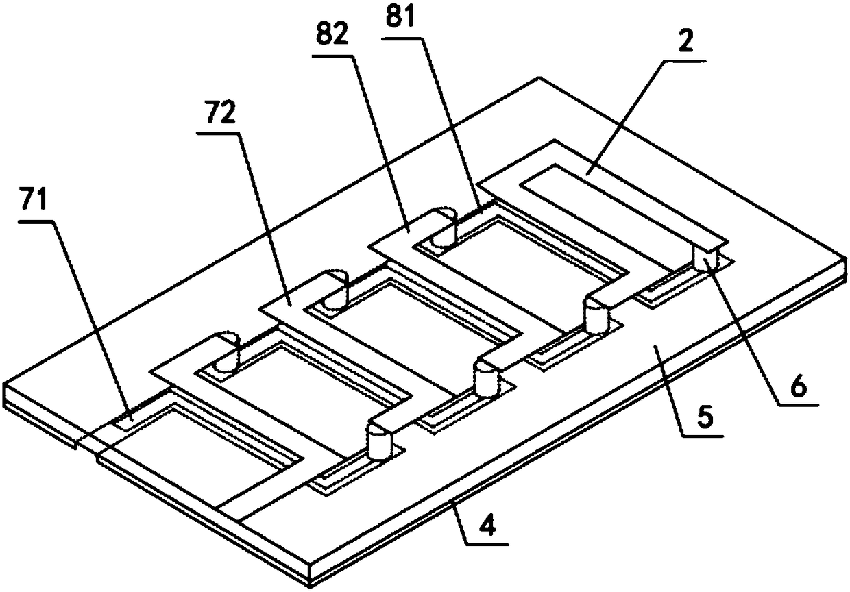
[0044] like Figure 1 to Figure 14 As shown, a miniaturized power splitter according to the present invention includes two power branches, an input transmission line 1, two microstrip connection units, two output ports 3, a metal floor 4, a dielectric board 5 and several Metal conductive vias 6, the metal conductive vias 6 run through the upper and lower surfaces of the dielectric board 5, the metal floor 4 is arranged on the lower surface of the dielectric board...


PUM


Abstract

The invention relates to the field of electronic devices, in particular to a miniaturized power divider. The miniaturized power divider comprises two power dividing branches, micro-strip connecting units, a medium plate and a plurality of metal conductive via holes, each power dividing branch comprises a forward circuit and a reverse circuit which are connected through the corresponding micro-strip connecting unit, each forward circuit comprises forward micro-strip-coplanar waveguide transmission units which are connected end to end, and each reverse circuit comprises reverse micro-strip-coplanar waveguide transmission units which are connected end to end; each forward micro-strip-coplanar waveguide transmission unit comprises a micro-strip transmission line section and a coplanar waveguide transmission line section which are connected end to end through the corresponding metal conductive via holes, each micro-strip transmission line section is located at the top of the medium plate, and each coplanar waveguide transmission line section is located at the bottom of the medium plate; each reverse micro-strip-coplanar waveguide transmission unit comprises a micro-strip transmission line section and a coplanar waveguide transmission line section which are connected end to end through the corresponding metal conductive via holes, each micro-strip transmission line section is locatedat the top of the medium plate, and each coplanar waveguide transmission line section is located at the bottom of the medium plate. The miniaturized power divider has the advantages that the double-layer micro-strip-coplanar waveguide Z-shaped cross transmission lines are adopted, and miniaturization of the power divider is achieved.

Description

technical field [0001] The invention relates to the field of electronic devices, in particular to a miniaturized power divider. Background technique [0002] With the increasing demand for miniaturization of microwave systems and equipment, the miniaturization of radio frequency devices has attracted more and more attention, and the miniaturization of the transmission line that constitutes the main structure of radio frequency devices is a key factor in determining the size of radio frequency devices. [0003] The power splitter (also called power divider) is used in the radio frequency link to meet special functional requirements (such as the feed network of large array antennas) to divide one radio frequency signal into two or more outputs with equal or unequal energy The radio frequency device can also combine two or more signal energies into one output, which is also called a combiner at this time. [0004] The power divider is one of the indispensable devices in variou...

Claims


Application Information

Patent Timeline
Patent Type & Authority Applications(China)
IPC IPC(8): H01P5/16
CPCH01P5/16
Inventor 钟国麟李园园宋传旺田海燕李言胜张春蘶
Owner QINGDAO TECHNOLOGICAL UNIVERSITY
Why Eureka
Try Eureka