Improved safety power transmission device

An improved and safe technology, applied in the direction of coupling device, connecting device components, circuits, etc., can solve the problems of life danger, impact of household appliances, falling, etc., achieve high safety of electricity consumption, reduce safety hazards, structure simple effect

Inactive Publication Date: 2018-06-29
罗志杰
View PDF4 Cites 2 Cited by
  • Summary
  • Abstract
  • Description
  • Claims
  • Application Information

AI Technical Summary

Problems solved by technology

[0002] With the continuous increase of household appliances, the number of power supply bases in the home is also increasing. When the room is decorated, more power supply bases will be installed to meet the use of household appliances. The power supply bases are generally fixed on the wall. Among them, there are slots with openings facing outwards, the conductive sheet in the power supply base is directly connected to the mains, and the conductive rod will contact the conductive sheet when inserted into the slot, so as to realize the electrification of household appliances, but for some safety Weak consciousness, such as infants and young children, will insert the metal rod into the slot ...

Method used


Image

  • Improved safety power transmission device
  • Improved safety power transmission device
  • Improved safety power transmission device

Examples


Embodiment Construction

[0026] All features disclosed in this specification, or all disclosed steps in a method or process, may be combined in any way except mutually exclusive features and / or steps.

[0027] Any feature disclosed in this specification (including any accompanying claims, abstract and drawings), unless expressly stated otherwise, may be replaced by other equivalent or alternative features serving a similar purpose. That is, unless expressly stated otherwise, each feature is but one example of a series of equivalent or similar features.

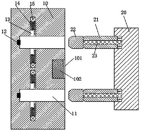
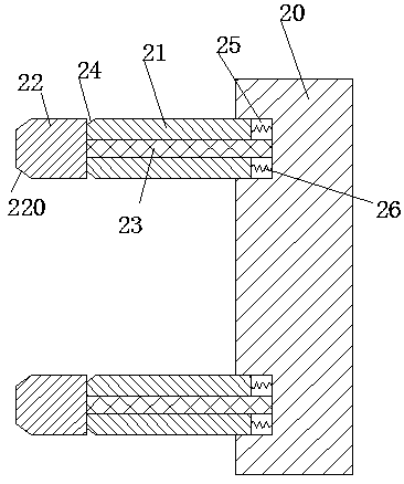
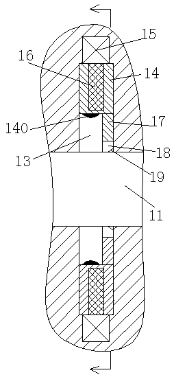
[0028] like Figure 1 to Figure 7 As shown, an improved safe power transmission device of the device of the present invention includes a power supply base 10 fixedly installed in the wall and a plug connector 20 matched with the power supply base 10. The left end surface of the plug connector 20 is A mounting cavity 25 with an opening facing the left end is symmetrically arranged in the middle, and a rectangular sliding sleeve 21 extending to the lef...


PUM


Abstract

The invention relates to an improved safety power transmission device. The improved safety power transmission device comprises a power supply base fixedly mounted in a wall body and a plug connector matched with the power supply base, wherein mounting cavities with openings facing the left end are vertically and symmetrically formed in the left end surface of the plug connector, each mounting cavity is slidably equipped with a rectangular sliding sleeve extending leftwards, a center hole is formed in each rectangular sliding sleeve, each center hole is slidably equipped with a conductive rod connected with a household electrical appliance, the right end of each conductive rod extends out of the corresponding rectangular sliding sleeve and is fixedly mounted in the right end wall of the corresponding mounting cavity, the left end of each conductive rod extends out of the corresponding rectangular sliding sleeve and is fixedly equipped with a rectangular conductive block, the left end ofeach rectangular sliding sleeve is vertically and symmetrically provided with pressed inclined surfaces, rectangular insertion grooves with openings facing rightwards and matched with the rectangularconductive blocks are vertically and symmetrically formed in the power supply base, sliding grooves facing the corresponding rectangular insertion groove are symmetrically formed in upper and lower end walls of each rectangular insertion groove, and a sliding block is slidably mounted in each sliding groove.

Description

technical field [0001] The invention relates to the field of electricity consumption of household appliances, in particular to an improved safe power transmission device. Background technique [0002] With the increasing number of household appliances, the power supply bases in the home are also increasing. More power supply bases will be installed in the room during decoration to meet the use of household appliances. The power supply bases are generally fixed on the wall. It is provided with a slot with an opening facing outward, the conductive sheet in the power supply base is directly connected to the mains, and the conductive rod is inserted into the slot to contact with the conductive sheet, so that the household appliances can be energized, but for some safety Weak consciousness, such as infants and young children, will insert the metal rod into the slot out of curiosity. Once the metal rod is inserted into the slot, it will also contact the conductive sheet. Therefore...

Claims


Application Information

Patent Timeline
IPC IPC(8): H01R13/60H01R13/639H01R13/703
CPCH01R13/60H01R13/639H01R13/7035
Inventor 罗志杰
Owner 罗志杰
Why Eureka
Try Eureka