USB cable, USB interface and adapter

A technology of USB interface and adapter, which is applied in the direction of connection, parts of connecting device, protective grounding/shielding device of connecting parts, etc., can solve problems such as poor compatibility of USB interface

Active Publication Date: 2018-06-29
MEIZU TECH CO LTD
View PDF7 Cites 46 Cited by
  • Summary
  • Abstract
  • Description
  • Claims
  • Application Information

AI Technical Summary

Problems solved by technology

[0006] The embodiment of the present application provides a USB cable, a USB interface, and an adapter to solve the current problem of poor compatibility between the first type of USB interface and the second type of USB interface.

Method used


Image

  • USB cable, USB interface and adapter
  • USB cable, USB interface and adapter
  • USB cable, USB interface and adapter

Examples


Embodiment 1

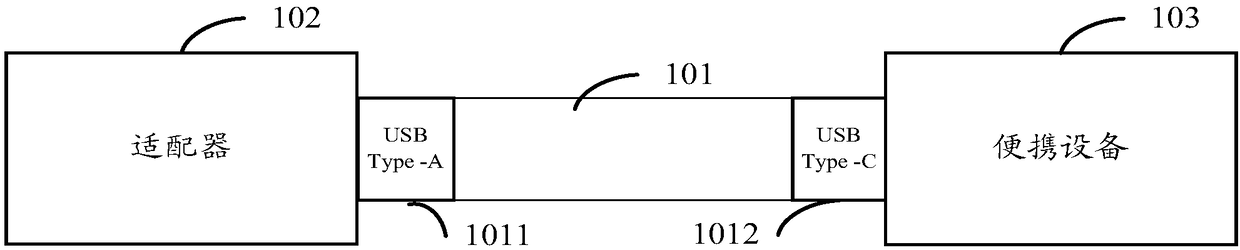
[0070] The inventor found through research that the cable from the USB Type-C interface to the USB Type-C interface is a conceptual product that supports the PD communication protocol. Due to some factors, the popularization of this product will take time. Currently, cables from the first type of USB interface to the second type of USB interface are used more often. How to support the PD communication protocol in the cable from the first type of USB interface to the second type of USB interface to improve its compatibility needs to be solved.

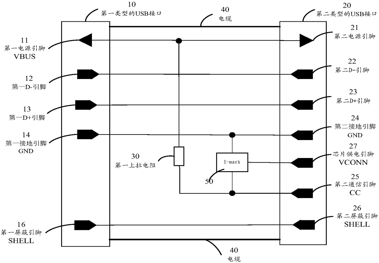
[0071] After research, the inventor found that the USB Type-C interface to USB Type-C interface does not exist figure 1 The first pull-up resistor is around 56KΩ (kilohms). Based on the different requirements of the two cables, an improved cable is provided in the embodiment of the present application.

[0072] Such as Figure 2A As shown in FIG. 2 , it is a structural schematic diagram of converting the first type of USB interface ...

Embodiment 2

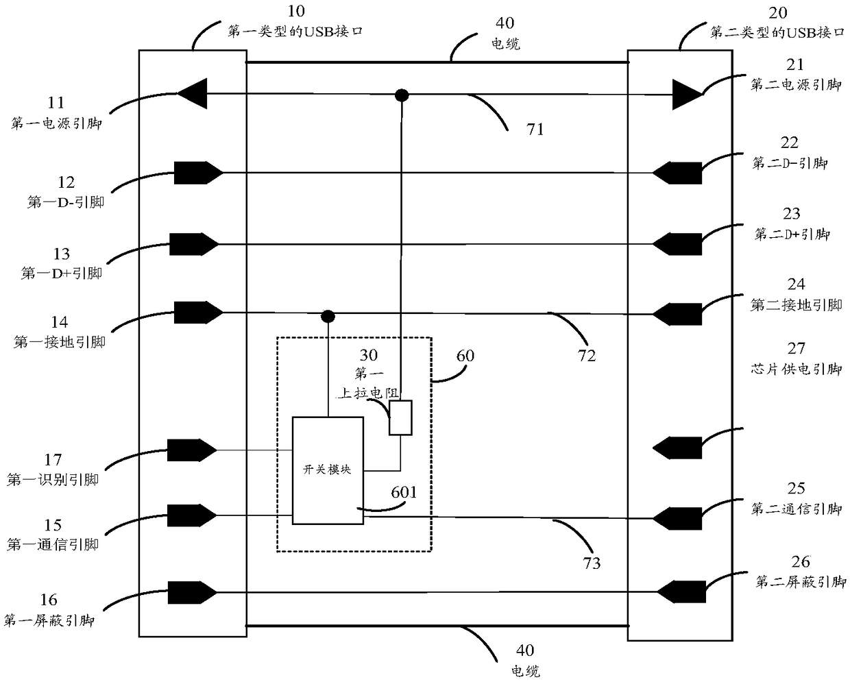
[0124] Based on the same inventive concept, the embodiment of the present application also provides a first type of USB interface 10 such as Figure 7 As shown, it includes a first type of USB interface 10 body with a first power supply pin 1111 (this body is as Figure 2A The first type of USB interface 10) also includes a first communication pin 15 and a first identification pin 17; wherein:

[0125] Including a first type of USB interface 10 body with a first power pin 1111 and a first ground pin 14, and also includes a first communication pin 15 and a first identification pin 17; wherein:

[0126] The first power pin 1111 is used to connect to the second power pin 21 of the second type of USB interface 20 through the power line 71;

[0127] The first communication pin 15 is used to connect with the second communication pin 25 of the second type of USB interface 20 through the communication signal line 73;

[0128] The first ground pin 14 is used to connect to the second ...

Embodiment 3

[0133] Based on the same inventive concept, the embodiment of the present application also provides an adapter suitable for the cable described in the embodiment of the present application, such as Figure 8 As shown, including the adapter body (not shown in the figure) and the adapter interface 90:

[0134]The adapter interface 90 is provided with a second pull-up resistor 91, a third power supply pin 92 and a second identification pin 93, wherein:

[0135] The second identification pin 93 is connected to the power line 71 of the third power supply pin 92 through the second pull-up resistor 91, and is used to insert the USB interface 10 of the first type in the adapter (in the figure not shown), the second identification pin 93 is connected to the (not shown in the figure) first identification pin 17, so that when the first identification pin 17 is at the first level, the The switch module 601 (not shown in the figure) is in the first state.

[0136] Based on the same inven...


PUM


Abstract

The invention discloses a USB cable, a USB interface and an adapter. A first identification pin used for identifying the cable as the conventional first-type-USB-interface-to-second-type-USB-interfacecable is additionally arranged on the first type USB interface to support the demand of identifying the first-type-USB-interface-to-second-type-USB-interface. A switch module and a first communication pin are additionally arranged to control connection and disconnection between a first pull-up resistor and a communication signal line and connection and disconnection between the first communication pin and a second communication pin so as to realize compatibility of the PD communication protocol and the conventional first-type-USB-interface-to-second-type-USB-interface.

Description

technical field [0001] The present application relates to the technical field of communication control, in particular to a USB cable, a USB interface and an adapter. Background technique [0002] Ordinary adapters, desktop computers, and laptops are still USB Type-A interfaces, that is, interfaces that do not support blind insertion on both sides. However, with the development of technology, the existing USB Type-C interface supports blind insertion on both sides, and is being promoted and applied to portable devices. [0003] At the same time, with the development of charging technology for portable devices, the requirements for charging cables are also increasing. Especially direct charging, in addition to the requirements on the voltage and current of the cable, it also requires real-time exchange of information between the portable device and the adapter to ensure safe and efficient charging. There are two ways to exchange information between portable devices and adapt...

Claims


Application Information

Patent Timeline
Patent Type & Authority Applications(China)
IPC IPC(8): H01R31/06H01R12/71H01R13/652H01R13/703
CPCH01R12/71H01R13/652H01R13/703H01R31/065
Inventor 谭琴刘小勇
Owner MEIZU TECH CO LTD
Why Eureka
Try Eureka