
Power distribution cabinet with heat dissipation function

A power distribution cabinet and functional technology, which is applied in substation/power distribution device casing, electrical components, substation/switch layout details, etc., can solve the problem of reducing the heat dissipation performance of the power distribution cabinet, reducing the service life of the power distribution cabinet, and power distribution cabinet equipment. Problems such as deterioration of the use effect, to achieve the effect of ensuring the normal use environment, prolonging the service life, and simple structure

Inactive Publication Date: 2018-06-29
佛山杰致信息科技有限公司
View PDF0 Cites 6 Cited by
  • Summary
  • Abstract
  • Description
  • Claims
  • Application Information

AI Technical Summary

Problems solved by technology

However, a large amount of dust tends to accumulate inside the existing power distribution cabinets, which not only reduces the aesthetics and usability of the power distribution cabinets, but more importantly, causes the equipment in the power distribution cabinets to deteriorate and be easily damaged. In addition, Too much dust will also reduce the heat dissipation performance of the power distribution cabinet. In addition, the existing power distribution cabinets generally have the defect of poor heat dissipation. Excessive dust will reduce the service life of the power distribution cabinet and cause accidents easily. Therefore, We propose a power distribution cabinet with heat dissipation

Method used


Image

  • Power distribution cabinet with heat dissipation function
  • Power distribution cabinet with heat dissipation function

Examples


Embodiment Construction

[0015] The technical solutions in the embodiments of the present invention will be clearly and completely described below in conjunction with the accompanying drawings in the embodiments of the present invention. Obviously, the described embodiments are only a part of the embodiments of the present invention, rather than all the embodiments.

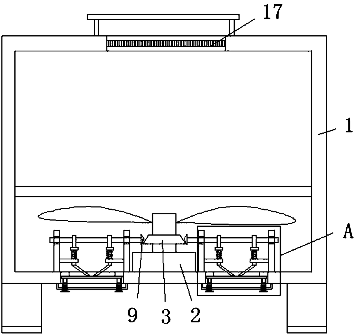
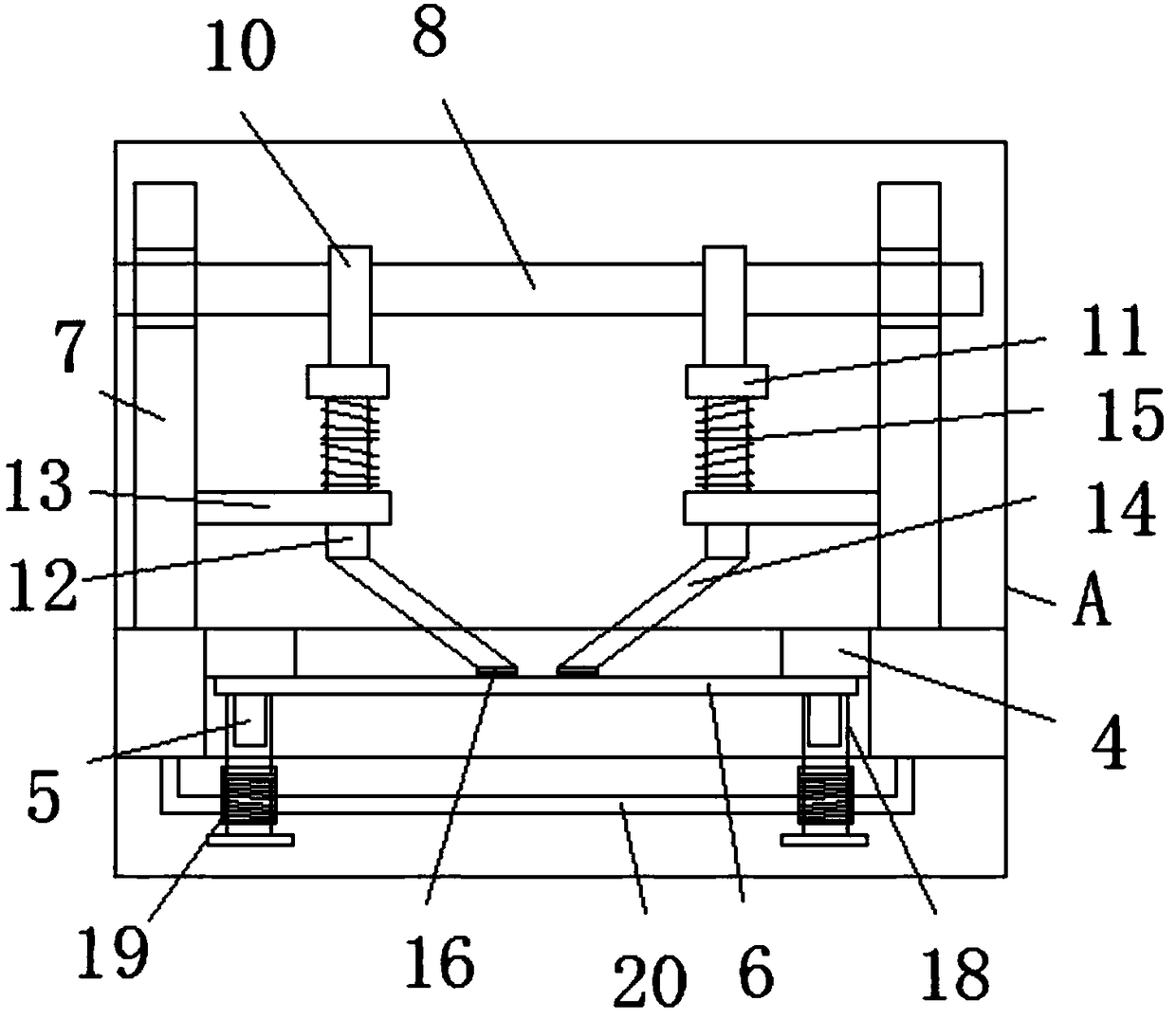
[0016] Reference Figure 1-2 , A power distribution cabinet with heat dissipation function, including a housing 1, the bottom inner wall of the housing 1 is mounted with a motor 2 arranged in a vertical direction, the outer ring of the output shaft of the motor 2 is fixedly sleeved with a first gear 3, the motor 2 are symmetrically opened with air inlets located at the bottom of the housing 1. The inner wall of the air inlet is welded with a symmetrical fixing block 4, and the bottom of the fixing block 4 is welded with a support rod 5 arranged in the vertical direction. The outer ring is movably sleeved with a first filter screen 6, and a ...


PUM


Abstract

The invention discloses a power distribution cabinet with a heat dissipation function, which comprises a shell, an electromotor which is arranged along a vertical direction is mounted on the inner wall of the bottom of the shell, a first gear is fixedly sleevedly connected with the periphery of the output shaft of the electromotor, air inlets which are located on the bottom of the shell are symmetrically arranged on both sides of the electromotor, fixed blocks which are symmetrically arranged are welded on the inner wall of each air inlet, supporting rods which are arranged along the verticaldirection are welded on the bottoms of the fixed blocks, a first filter screen is movably connected to the peripheries of the supporting rods, and a fixing device is mounted on the side, which is farfrom the fixed blocks, of the first filter screen. On one hand, the power distribution cabinet can ensure that temperature in the cabinet body is not overhigh, ensuring that equipment in the power distribution cabinet can normally operate, on the other hand, the probability of dust entering the cabinet body is decreased, ensuring a normal operation environment for operating elements in the cabinetbody and prolonging the service lives of the operating elements in the cabinet body, moreover, the filter screens can be conveniently replaced, the structure is simple, and the power distribution cabinet is convenient to use.

Description

Technical field [0001] The present invention relates to the technical field of power distribution cabinets, in particular to a power distribution cabinet with heat dissipation function. Background technique [0002] The power distribution cabinet is an important device in the power system and the final equipment of the power distribution system. Power distribution cabinets are widely used in various industries. However, the existing power distribution cabinets tend to accumulate a lot of dust, which not only reduces the aesthetics and usability of the power distribution cabinets, but more importantly, causes the equipment in the power distribution cabinets to deteriorate and be easily damaged. In addition, Excessive dust will also reduce the heat dissipation performance of the power distribution cabinet. In addition, the existing power distribution cabinets generally have the defect of poor heat dissipation. Excessive dust will reduce the service life of the power distribution c...

Claims


Application Information

Patent Timeline
IPC IPC(8): H02B1/56H02B1/28
CPCH02B1/565H02B1/28
Inventor 王玉环
Owner 佛山杰致信息科技有限公司
Learn More