
Optical network protection control method, optical network protection control device and network management server

A technology of protection control and optical network, which is applied in the field of communication, can solve problems such as not being able to meet the needs of network development, and achieve the effect of reliable optical network protection

Active Publication Date: 2018-06-29
ZTE CORP
View PDF7 Cites 2 Cited by
  • Summary
  • Abstract
  • Description
  • Claims
  • Application Information

AI Technical Summary

Problems solved by technology

[0007] An optical network protection control method, device and network management server provided by the embodiment of the present invention mainly solve the technical problem that the existing optical network protection is only It is triggered based on the change of optical power due to the sudden loss of optical signal, which cannot well meet the needs of network development.

Method used


Image

  • Optical network protection control method, optical network protection control device and network management server
  • Optical network protection control method, optical network protection control device and network management server
  • Optical network protection control method, optical network protection control device and network management server

Examples


Embodiment 1

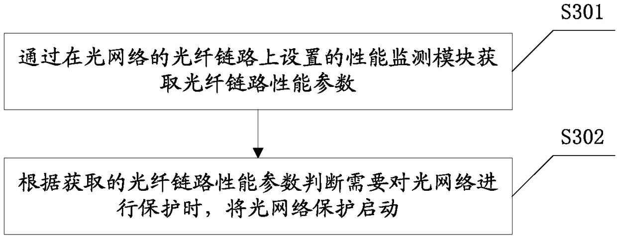
[0032] For the optical network protection control method provided in this embodiment, refer to image 3 shown, including:

[0033] S301: Obtain the performance parameter of the optical fiber link through the performance monitoring module set on the optical fiber link of the optical network.

[0034] When the output end of the performance monitoring module in this embodiment is set on the optical fiber link, it can be coupled and connected to the output end of the amplifier on the optical fiber link. Specifically, various performance monitoring equipment can be used to acquire performance parameters. The optical fiber link performance parameters in this embodiment may include at least one of optical fiber performance parameters and optical signal transmission performance parameters, for example, may directly include optical fiber performance parameters and optical signal transmission performance parameters. Optical fiber performance parameters can be obtained through OTDR (Op...

Embodiment 2

[0063] This embodiment provides a network management server, see Figure 4 As shown, the optical network protection control device 1 is included, and the optical network protection control device 1 can obtain the performance parameters of the optical fiber link and serve as a trigger for triggering the optical network protection, so as to provide more comprehensive and reliable optical network protection. see Figure 5 As shown, the optical network protection control device 1 in this embodiment includes:

[0064] The performance parameter acquiring module 11 is configured to acquire the performance parameter of the optical fiber link through the performance monitoring module set on the optical fiber link of the optical network. When the output end of the performance monitoring module in this embodiment is set on the optical fiber link, it can be coupled and connected to the output end of the amplifier on the optical fiber link. The optical fiber link performance parameters i...

Embodiment 3

[0091] In order to better understand the present invention, an example of the present invention will be described below with two specific application scenarios.

[0092] see Image 6 Shown is an optical fiber link added with a performance monitoring module according to an embodiment of the present invention. The performance monitoring module in this embodiment integrates OTDR and OPM functions, and its output end is coupled with the output end of an optical fiber amplifier. And physically, the performance monitoring module can be integrated with the fiber amplifier, see Figure 11 As shown, the performance monitoring module can also be set separately from the fiber amplifier. The performance monitoring module is used in conjunction with the fiber amplifier. See Figure 12 shown.

[0093] The "×" between T1 and R2 indicates that there is a fault in this section; fiber amplifiers include but are not limited to Raman Fiber Amplifier (RFA), Erbium-doped Optical Fiber Amplifier (...


PUM


Abstract

The embodiment of the invention provides an optical network protection control method, an optical network protection control device and a network management server. The optical network protection control method comprises the steps of: obtaining performance parameters of an optical fibre link through a performance monitoring module arranged on the optical fibre link of an optical network, wherein the obtained performance parameters of the optical fibre link include at least one of an optical fibre performance parameter and an optical signal transmission performance parameter; and, judging whether the optical network needs to be protected or not currently according to the obtained performance parameters of the optical fibre link, and if so, starting optical network protection, wherein the started optical network protection includes at least one of automatic power reduction protection and automatic switched protection. Visibly, the performance parameters of the optical fibre link can be obtained; on this basis, whether starting of the optical network protection is triggered or not is judged; therefore, attention requirements of operators on the optical network performance can be satisfied; and relatively comprehensive and reliable optical network protection can be provided.

Description

technical field [0001] The invention relates to the communication field, in particular to an optical network protection control method, device and network management server. Background technique [0002] In optical communication systems, optical power is lost due to accidents such as fiber cut, equipment failure, or optical connector pulling out. On the one hand, for the sake of personnel safety, the APR (Automatic Power Reduction, automatic power reduction) protection process will be started when the optical power in an optical transmission section of the main optical channel is lost. After the optical fiber link is normal, the communication will automatically resume, and the APR optical power It is required to meet the standards of BSEN 60825-1-1994 and BSEN 60825-2-2000. On the other hand, for the sake of system protection, APS (Automatic Protection Switched) is generally added to the optical transmission link. When the working link fails, it will automatically switch to...

Claims


Application Information

Patent Timeline
Patent Type & Authority Applications(China)
IPC IPC(8): H04B10/032H04B10/071
CPCH04B10/032H04B10/071
Inventor 康杰朱晓宇
Owner ZTE CORP
Learn More