
Eccentric positioning platform

A positioning platform and eccentric technology, applied in the direction of electrical components, printed circuit manufacturing, printed circuit, etc., can solve the problems of high production cost, slow platform positioning speed, etc., and achieve the effect of saving manufacturing cost

Pending Publication Date: 2018-06-29
深圳市隆阳自动化设备有限公司
View PDF0 Cites 1 Cited by
  • Summary
  • Abstract
  • Description
  • Claims
  • Application Information

AI Technical Summary

Problems solved by technology

There is no need for manual intervention in the alignment process, which saves the labor cost of the enterprise and improves the production quality of the product. However, the platform needs to use at least four sets of motors and shafts, which has high production costs, and the positioning speed of the platform is slow. Four XYθ alignment The unit cannot quickly locate the working platform

Method used


Image

  • Eccentric positioning platform
  • Eccentric positioning platform
  • Eccentric positioning platform

Examples


Embodiment 1

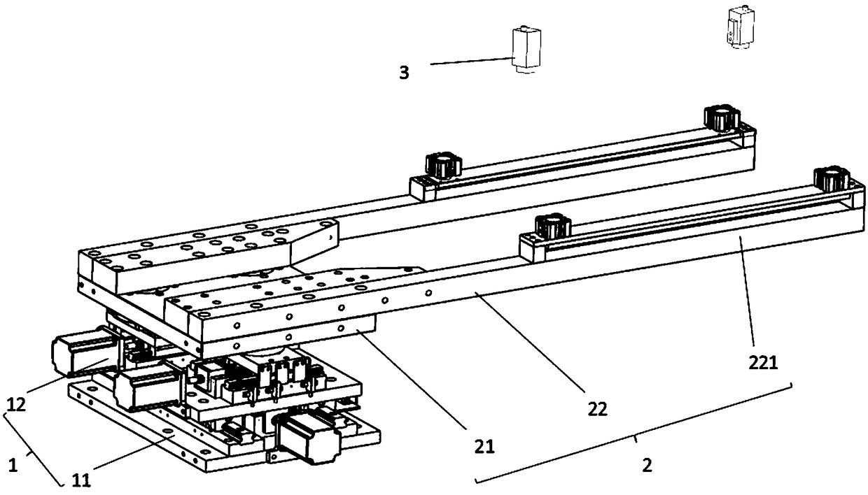
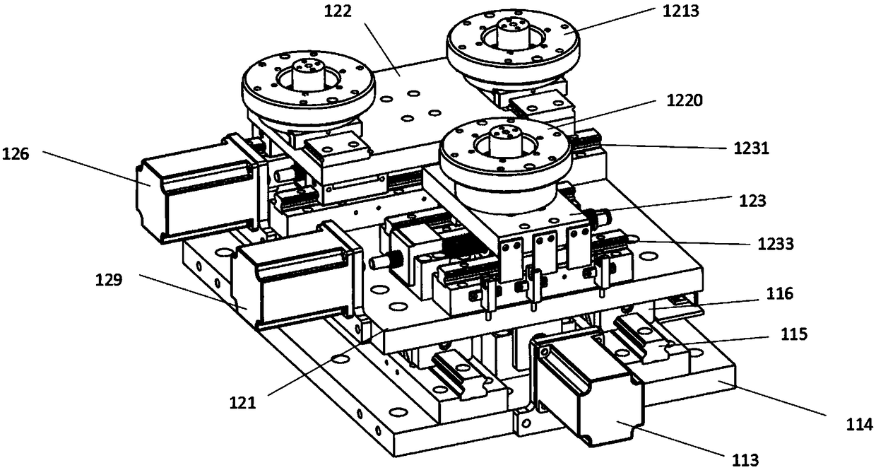
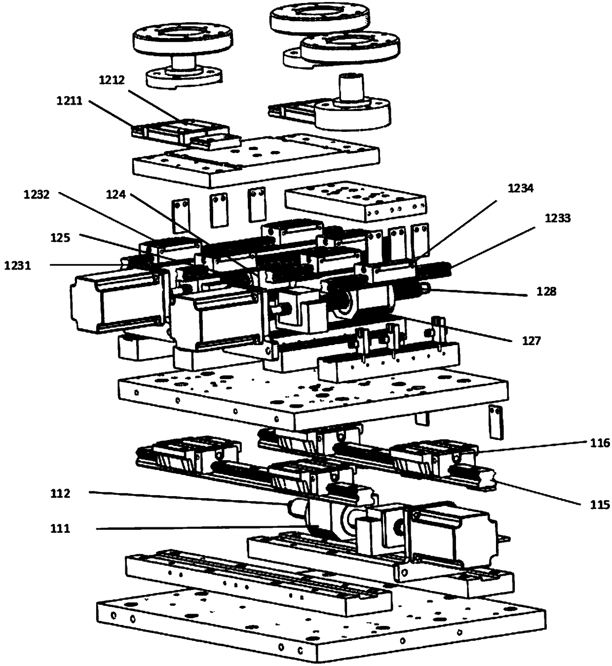
[0024] Such as figure 1 As shown, it is a kind of eccentric positioning platform provided by the present invention, which is used for processing and positioning of workpieces, including positioning driving device 1, workpiece support platform 2, controller and CCD camera 3 electrically connected with the controller (in the figure The support structure of the camera is omitted), wherein the workpiece support platform 2 is installed on the positioning drive device 1 . The positioning driving device 1 includes a translation positioning mechanism 11 that drives the workpiece support platform 2 to perform left and right translational motions and a side deviation correction mechanism 12 that drives the workpiece support platform 2 to perform left and right deflection movements. The support plate 21 directly above and the support arms 22 arranged in parallel and spaced apart, one end of the two support arms are respectively fixed on the support plate 21, and the other ends jointly fo...

Embodiment 2

[0033] Such as Figure 5 As shown, the difference between the present embodiment and the first embodiment is that the CCD camera 3 of the present embodiment (the supporting structure of the camera is omitted in the figure) is arranged below the bearing end 221, and the CCD camera takes pictures of the workpiece from below the workpiece and The difference between the position of the workpiece and the reference position is calculated, and the rest are the same as those in Embodiment 1, and will not be repeated here.

[0034] The eccentric positioning platform provided by the embodiment of the present invention can identify the deviation between the workpiece and the reference position by photographing the workpiece on the workpiece loading end with a CCD camera. The controller controls the positioning drive device to drive the workpiece support platform to move, and the workpiece support platform is positioned in translation Driven by the mechanism and the side deviation correct...


PUM


Abstract

The invention discloses an eccentric positioning platform used for positioning workpieces in machining. The eccentric positioning platform comprises a controller, a CCD camera, a workpiece supportingplatform and a positioning driving device, wherein the CCD camera, the workpiece supporting platform and the positioning driving device are electrically connected with the controller separately; the workpiece supporting platform is arranged on the positioning driving device; the positioning driving device comprises a horizontal movement positioning mechanism for driving the workpiece supporting platform to horizontally move left and right, and a side deviation correcting mechanism for driving the workpiece supporting platform to perform left and right deflection movements; the workpiece supporting platform comprises a supporting plate arranged over the positioning driving device, and two supporting arms arranged at an interval in parallel; one end of each supporting arm is fixedly arrangedon the supporting plate, and the other end of one supporting arm and the other end of the other supporting arm jointly form a workpiece bearing end to carry a workpiece; the CCD camera is arranged over or under the workpiece bearing end. According to the eccentric positioning platform, the manufacturing cost of a positioning mechanism can be reduced, and rapid and automatic positioning can be achieved.

Description

technical field [0001] The invention relates to the technical field of automatic alignment devices, in particular to an eccentric positioning platform. Background technique [0002] At present, in the field of printed circuit board production, due to the high precision requirements for the positioning of circuit boards during the production process, it is difficult for current equipment to achieve this precision requirement, so its production has always relied on manual operations, especially in positioning operations. By drilling positioning holes on the circuit board, and then cooperating with the positioning columns on the equipment, the positioning of the production products is realized by manual positioning and installation. The above-mentioned production steps not only have a low degree of automation and require a lot of manpower and material resources, but also have poor positioning accuracy and cannot realize repeated and rapid sequential production and manufacturing...

Claims


Application Information

Patent Timeline
Patent Type & Authority Applications(China)
IPC IPC(8): H05K3/00
CPCH05K3/00H05K2203/0147H05K2203/1509
Inventor 夏小辉贺翀兰小艳陈小艳邬燕
Owner 深圳市隆阳自动化设备有限公司
Learn More