
Practical self-fixation welding device

A welding device and self-fixing technology, applied in auxiliary devices, welding equipment, auxiliary welding equipment, etc., can solve problems such as easy offset, displacement of welding parts, reduction of production efficiency and product qualification rate, etc., to achieve accuracy And high precision, improve production efficiency, high stability effect

Inactive Publication Date: 2018-07-03
广州子赫建筑装饰有限公司
View PDF5 Cites 0 Cited by
  • Summary
  • Abstract
  • Description
  • Claims
  • Application Information

AI Technical Summary

Problems solved by technology

[0002] In the process of welding circuit boards and other welding parts, it is difficult for workers to take into account the fixing of the welding parts, which leads to the displacement of the welding parts during the welding process and affects the welding. The clamping parts of some welding machines generally need to be manually fixed, which is time-consuming and laborious , and the fixing effect is not good, and it is easy to shift, which cannot effectively solve the problem of fixing the welding parts, which reduces the production efficiency and product qualification rate

Method used


Image

  • Practical self-fixation welding device
  • Practical self-fixation welding device
  • Practical self-fixation welding device

Examples


Embodiment Construction

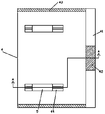
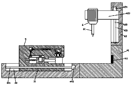
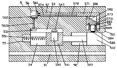
[0030] Such as Figure 1-Figure 10As shown, a practical self-fixing welding device of the present invention includes a base body 4, and first sliding grooves 44 are arranged on the front and rear top surfaces of the base body 4 in proportion, and each of the first sliding grooves 44 is slidingly fitted and connected with The top extends to the clamping mechanism 5 outside the top surface of the base body 4. The clamping mechanism 5 in the first sliding groove 44 is provided with a first screw hole 51 extending left and right. The first screw hole The clamping mechanism 5 above 51 is provided with a first sliding cavity 54, the top of the first sliding cavity 54 is connected with a first conversion cavity 53, and a sliding block 541 is slidingly connected in the first sliding cavity 54. , the right side of the clamping mechanism 5 on the right side of the first sliding cavity 54 is provided with a clamping sliding groove 52, and a pushing block 522 is slidingly connected in the...


PUM


Abstract

The invention discloses a practical self-fixation welding device. The practical self-fixation welding device comprises a basal body; first sliding grooves are symmetrically arranged in the front and back top surfaces of the basal body; clamping mechanisms with tops extending out of the top surface of the basal body are slidingly matched and connected into the two first sliding grooves; first screwholes extending left and right are formed in the clamping mechanisms in the first sliding grooves; first sliding cavities are formed in the clamping mechanisms above the first screw holes; first conversion cavities communicate to the tops of the first sliding cavities; sliding blocks are slidingly connected into the first sliding cavities; clamping sliding grooves are formed in the right side surfaces of the clamping mechanisms on the right sides of the first sliding cavities; pushing blocks are slidingly connected into the clamping sliding grooves; locking motors are fixedly arranged in thetop surfaces of the sliding blocks; the tops of the locking motors are matched and connected with first bevel gears extending into the first conversion cavities; and second conversion cavities are arranged in the clamping mechanisms above the left sides of the first conversion cavities. The practical self-fixation welding device is simple in structure, saves both time and labors, is not easy to generate deviation, and improves the production efficiency.

Description

technical field [0001] The invention relates to the field of welding technology, in particular to a practical self-fixing welding device. Background technique [0002] In the process of welding circuit boards and other welding parts, it is difficult for workers to take into account the fixing of the welding parts, which leads to the displacement of the welding parts during the welding process and affects the welding. The clamping parts of some welding machines generally need to be manually fixed, which is time-consuming and laborious , and the fixing effect is not good, and it is easy to shift, which cannot effectively solve the problem of fixing the welding parts, which reduces the production efficiency and product qualification rate. Contents of the invention [0003] The technical problem to be solved by the present invention is to provide a practical self-fixing welding device, which can solve the above-mentioned problems in the prior art. [0004] The present inventi...

Claims


Application Information

Patent Timeline
IPC IPC(8): B23K3/08B23K37/04
CPCB23K3/087B23K37/04
Inventor 冯斌斌
Owner 广州子赫建筑装饰有限公司
Learn More