
Valve mechanism

A valve and valve body technology, applied in the mechanical field, can solve problems such as difficulty in opening the valve core and wear of the valve core

Pending Publication Date: 2018-07-03
XINXING HEAVY IND HUBEI 3611 MECHANICAL
View PDF8 Cites 1 Cited by
  • Summary
  • Abstract
  • Description
  • Claims
  • Application Information

AI Technical Summary

Problems solved by technology

[0002] At present, the refueling gun has only one spool. When the pressure in the gun body is high, it will be difficult to open the spool; and the spool moves back and forth frequently, which will cause the spool to wear

Method used


Image

  • Valve mechanism
  • Valve mechanism
  • Valve mechanism

Examples


Embodiment Construction

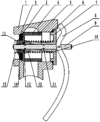
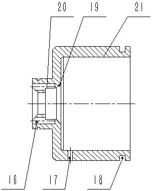
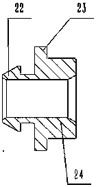
[0020] figure 1 , 2 , 3, the present invention includes a valve body 1, a main shaft 9 located in the valve body, a main valve core 4 assembled on the main shaft 9, a pressure relief valve core (also called a small valve core) 12, a cover 7, assembled on the main shaft 9 The pin shaft 15 at the front end is assembled on the handle 8 at the rear end of the main shaft 9 . A shaft sleeve 14 is arranged between the main valve core 4 and the main shaft 9 . The front end of the main valve core 4 is equipped with a large sealing gasket 3, and the front end of the large sealing gasket 3 is equipped with a pressure pad 2. The end is fitted with a piston ring 5. A spring 10 is assembled between the small valve core 12 and the cover 7, and a large sealing ring 6 is installed on the cover 7. A small gasket 13 is assembled on the small spool 12 . A small sealing ring 11 is provided between the cover 7 and the main shaft, and between the pressure relief valve core 12 and the main shaft...


PUM


Abstract

The invention discloses a valve mechanism. The valve mechanism comprises a valve body, and a valve element assembly is installed at an outlet of the valve body; the valve element assembly is installedin the middle of a spindle in a sleeving mode, one end of the spindle is provided with a handle, and the other end of the spindle is provided with a stopping portion used for cooperating with the handle to push the valve element assembly to move; and the valve element assembly comprises a main valve element, the main valve element is provided with a liquid filling hole and an overflow hole, the valve element assembly further comprises a pressure relieving valve element used for communicating with the liquid filling hole and the overflow hole to complete pressure relieving and a spring used for supporting the pressure relieving valve element, the pressure relieving valve element is located in the main valve element, one end of the spring abuts against the pressure relieving valve element,and the other end of the spring abuts against a sealing cover installed on the valve body. The valve mechanism has the characteristics of being simple and compact in structure and convenient to use. When the valve mechanism frequently moves back and forth, the service life of the valve element is mainly prolonged through friction between a piston ring and a valve body.

Description

technical field [0001] The invention belongs to the technical field of machinery, and in particular relates to a valve mechanism. Background technique [0002] At present, the refueling gun has only one spool. When the pressure in the gun body is high, the spool will be difficult to open; and the spool moves back and forth frequently, which will cause the spool to wear. Contents of the invention [0003] The object of the present invention is to overcome the above shortcomings of the prior art and provide a valve mechanism with the characteristics of simple structure, compactness and convenient use. [0004] The technical solution of the present invention is: a valve body is included, and a valve core assembly is installed at the outlet of the valve body; The moving stop part of the assembly; the spool assembly includes a main spool, the main spool is provided with a filling hole and an overflow hole, and the spool assembly also includes a hole to complete the pressure r...

Claims


Application Information

Patent Timeline
Patent Type & Authority Applications(China)
IPC IPC(8): F16N23/00F16K1/36F16K31/60F16K1/52
CPCF16K1/36F16K1/52F16K31/602F16N23/00
Inventor 马远洋张瑜张新智
Owner XINXING HEAVY IND HUBEI 3611 MECHANICAL
Learn More